D3D Printer Design Process: Difference between revisions
| Line 103: | Line 103: | ||
| align="right" | 0.070 | | align="right" | 0.070 | ||
| align="left" | m/s | | align="left" | m/s | ||
| | | [[Stepper Motor]] generally don't want to run faster than 300 rev/min. Threaded rods that's more aggressive than 14-15 mm per revolution are hard to source. | ||
|- | |- | ||
| '''Max acceleration: ''' | | '''Max acceleration: ''' | ||
| Line 119: | Line 119: | ||
Newton's second law gives maximum force needed: | Newton's second law gives maximum force needed: | ||
F = (0.74 * 5)/0.6 = 6.16 N | F = (0.74 * 5)/0.6 = 6.16 N | ||
The lever length of is ~3.5 mm, so torque on stepper motor is 0.022 Nm = 2.2 Ncm. | |||
Let's do some more pessimistic assumptions: lead screw efficiency at 20 %, skewed weight distribution of Y-axis gives double max weight: 1.3 kg. Accelerations of 9 m/s^2. This gives a force of 58.5 N and a torque of 20.5 Ncm, which is still within stepper motor limits at max speed (70 mm/s) for three of the four tested Nema17 stepper motor models tested [http://reprap.org/wiki/Stepper_torque here]. | |||
We conclude that a Nema17 | |||
== 3D Printer Signature == | == 3D Printer Signature == | ||
Revision as of 15:52, 9 January 2016
This document lists D3D Printer Design decisions and reasoning behind them in chronological order. The intention is to make the process as debuggable as possible and facilitate later creation of formal documents such as Design Decision Tree and Conceptual Design diagrams. It follows the D3D_Design_Methodology.
Sources Driving Design Desicions in Priority Order
- D3D_Fusion_printer_design#Higher_Level_Goals
- D3D_Fusion_printer_design#Desired_Attributes
- D3D_Fusion_printer_design#Functional_Requirements
- RepRap Interface Standard
- The shape of the input determines the shape of the design and tests.[1]
Process
Concept Creation
This page was tagged as a candidate for deletion. If this page does not meet our criteria for deletion, please remove this notice.
'
Note Note: We started out this process with concept creation. This deviates from the D3D Design Methodology, but we document it here nontheless.
D3D_Printer_Design#Functional_Requirement nr 1 is that the printer should be buildable in one day, and a parallelizable build is highly desired. A random Youtube search around modularity in CNC machines led to discovering the concept of modular linear actuators, as shown by Alexander Stepanenko in a video. The concept would allow
- ... building linear actuators and other parts at the same time
- ... defining a ubiquitous standard (screw position) interface
Normally, we would reason here around advantages that the concept of modular linear actuators could provide, but OSE found its potential exciting enough to put it directly into D3D_Printer_Design#Functional_Requirements.
Instead of diving into stepwise definition of interface and linear actuator, we decided to grab the following low-hanging fruit:
- Standard Screw Interface: Nema17
- Linear Actuator: Stepper Motor + lead screw
Validation of lead screw + stepper motor
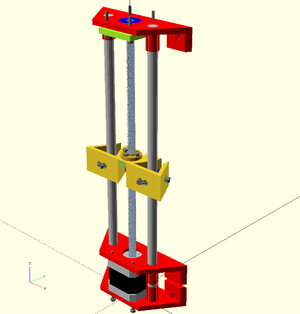
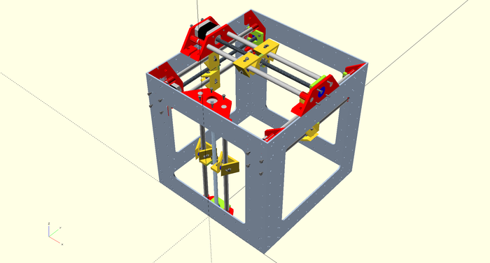
CAD viability
Looks sane...
Practical force viability
Finished and working all-leadscrew 3D printer printing at 75mm/s: https://www.youtube.com/watch?v=gk9lhcTGSH4
Theoretical force viability
Recall Newtons second law:
F = ma
Total linear actuator weight is approximated like
| Parameter | Estimated value | Unit | Source |
|---|---|---|---|
| Motor: | 0.4 | kg | [http://www.osmtec.com/nema_17_step_motor_17_hs.htm stepper motor shop |
| Lead screw/Smooth rod: | 0.12 | kg | density=8000 kg/m^3, radius=4 mm and length=300 mm |
| Linear Bearing | 0.015 | kg | linear bearing shop |
| Hot End | 0.05 | kg | hot end shop |
| X-Carriage (extruder + hot end): | 0.67 | kg | Hotend + Motor + Four linear bearings + 0.05 kg of plastic + 20 percent |
| Linear Actuator Module: | 0.81 | kg | Motor + two smooth rods + lead screw + 0.05 kg of plastic |
| Y-Carriage (X-Carriage + linear actuator module): | 1.48 | kg | Linear Actuator Module + X-Carriage |
The linear actuator will have to meet following circa-requirements to be realistic:
| Parameter | Value | Unit | Source |
|---|---|---|---|
| Weight load: | 0.74 | kg | Y-Carriage weight/2 |
| Max Speed: | 0.070 | m/s | Stepper Motor generally don't want to run faster than 300 rev/min. Threaded rods that's more aggressive than 14-15 mm per revolution are hard to source. |
| Max acceleration: | 5 | m/s^2 | Requirements/choice |
| Worst expected Lead screw efficiency: | 60 | % | CNC router source |
Torque from rotational inertia is not included in the table because inertia of the threaded rod is tiny (order of -7 kg m^2). Newton's second law gives maximum force needed:
F = (0.74 * 5)/0.6 = 6.16 N
The lever length of is ~3.5 mm, so torque on stepper motor is 0.022 Nm = 2.2 Ncm.
Let's do some more pessimistic assumptions: lead screw efficiency at 20 %, skewed weight distribution of Y-axis gives double max weight: 1.3 kg. Accelerations of 9 m/s^2. This gives a force of 58.5 N and a torque of 20.5 Ncm, which is still within stepper motor limits at max speed (70 mm/s) for three of the four tested Nema17 stepper motor models tested here.
We conclude that a Nema17
3D Printer Signature
Input: Power, Build material, Supporting surface(s), Instructions Output: Physical object
3D Printer Purpose Statement
A 3D printer is a machine that synthesizes build material into 3D objects according to a series of pre-determined instructions.
3D Printer Examples
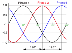
We will assume that a mains voltage will power the 3D printer, with the constant shape:


For the build material, we will assume filaments behaving roughly as thermoplastics with the constant shape: ...
- ↑ Cite error: Invalid
<ref>tag; no text was provided for refs namedhtdp

