Boundary Layer Turbine: Difference between revisions
| Line 117: | Line 117: | ||
The nozzle was formed out of bendable sheet metal and brazed together. It was then brazed to a 1" inlet pipe for the working gas. In order to form a venturi shape, a constriction was formed in the middle of the nozzle. | The nozzle was formed out of bendable sheet metal and brazed together. It was then brazed to a 1" inlet pipe for the working gas. In order to form a venturi shape, a constriction was formed in the middle of the nozzle. | ||
=Other Work= | |||
Look at a great example of a solar turbine (dish concentrator, bladed turbine) for comparison. The publication has many calculations that can be used for reference in other designs. By C. Christopher newton - [http://www.redrok.com/engine.htm#newton] | |||
=License= | =License= | ||
This design is open source. It is placed explicitly in the public domain for the benefit of all humankind. Our license is copyleft. We encourage any user of this information to place any further developments in the public domain for others to build on. | This design is open source. It is placed explicitly in the public domain for the benefit of all humankind. Our license is copyleft. We encourage any user of this information to place any further developments in the public domain for others to build on. | ||
Revision as of 16:41, 13 May 2008
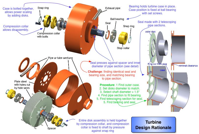
Design Rationale
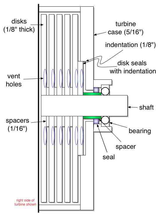
Drawings by Dan Granett, Granett Engineering:
This is an external combustion engine with proven efficiencies of 25% for un-optimized models with steam (Rice, Warren, Transactions of the ASME, Journal of Engineering and Power, January 1965, pp. 28-36). A working fluid spins this turbine by means of surface friction. When the disk spacing is small (on the scale of a millimeter), energy transfer from the working fluid to the disks can be efficient. Design rationale:
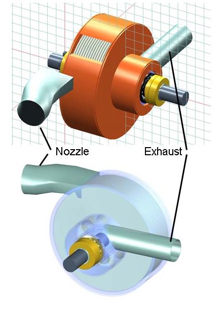
Working fluid (such as steam) enters tangentially to the disks through a nozzle:
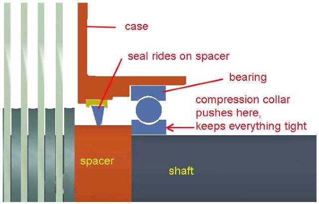
Bearings must be protected from the working fluid with a shaft seal seal:
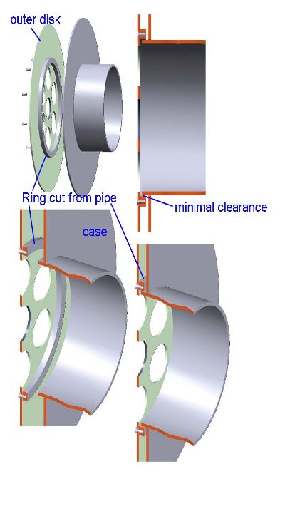
Working fluid must be prevented from escaping past the outer disks so that it can transfer its energy effectively to all the disks. To do this, we put in a ring seal:
Simplified Seal Design
The main seal (not the ballbearing seal) may be simplified as follows:
Bottom Line: Simplicity
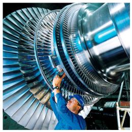
The bounary layer turbine is the simplest design of a turbine possible, and it has a respectable efficiency of 25% without optimization. For the significantly lower simplicity and cost, it's a competitor with bladed steam turbines. Compare this to the steam turbines of modern power plants, and you can appreciate the difference:
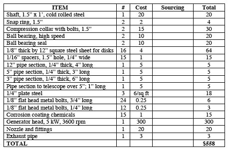
Bill of Materials: Boundary Layer Turbine
The materials cost for the boundary layer turbine, including generator head, is:
Development Log
See the Turbine Development Log.
Turbine Fabrication: General
Turbine Fabrication: Materials and Tolerances
Materials:
We begin with a shaft. It should be some form of hardened steel, either machinable hardened tool steel (using a carbide bit) or A36 that is subsequently hardened. Hardening may be performed by any form of surface treatment. If heat treatment is used for hardening, attention must be given to possible distortion.
The case can be any machinable steel. Zinc galvanization spray, gun-blue, black oxide, or nitriding may be used for corrosion resistance from steam.
Tolerances:
- Shaft: 1.500" +0.0000/-0.0005
- Disks: laser cut - see [here.]
- Radial spacing between disks and outer case: 10-20 thousandths of an inch
- Shaft and bearings end sections:
- Distance between shaft and ballbearing inner race: -0.0005/+0.000 inch
- Distance between outer race of bearning and housing: -0.000/+0.002 inch
- Spacer 1-2 thousandths tolerance around shaft
- Main seal disk: +/- 0.001 match to side circular plate; zinc coat on disk and side plate will make a perfect match
Sizes:
- Pipe section by bearings: 7/16-3/4" thick to accommodate bearings and seals; depends on bearing OD
Other Construction Details:
Prototype Adaptability:
The prototype of the present, simplified design should be made such that it can be modified readily. As already mentioned in Design Rationale, the entire assembly is held together by compression collars, where the collars are fixed in position by e-rings. Moreover, the pipe sections, including the exhaust shroud, should be bolted with countersunk bolts. As such, the entire device can be taken apart by taking off the e-ring, loosening the collar, unbolting the case, and the entire device can be taken apart.
Using this design, the device can be scaled and modified. Additional disks may be added for more power, and the outer case may be substituted with a longer one. Tolerances can be changed by replacing the case and other components. As such, the device is a testbed for modification. Each modification step requires the replacement of a part, not the entire machine.
- Use bolts for outer case, and for end case section
Gussets
Note that prior work has reinforcing gussets on the end plates. These gussets are avoided in this design by using thicker end plates, 5/16" thick. Gussets, if welded, give thermal distortion to the case.
Main Seal Disk
- 1/4 or 5/16 thick to provide maximum overlap with end circular plate
Nozzle
- Nozzle was brazed from workable sheet metal
- Inlet pipe: 1"
Other
- Use 3/16" bolts to bolt case together, or common #10 bolts
- Use stainless steel bolts for end pipe section - bolts in contact with steam
- Counterbore if use socket head cap screws
- Use red silicone seals between spacer and end pipe section; or use Parker o-rings
- Fabricate end pipe sections first, to fit the bearing and seals
- Match this to end circular plate, bolt it to end circular plate
- Countersink bolt holes for end pipe section; thread the end pipe section
Prior Work
A working model of this turbine has been built several years ago. This model was more involved with respect to the fabrication procedure. The present work is a simplification in design. See [here].
The prior work featured a turbine without seals between the outside rotor disk and the case. This means that the working gas was escaping partly out the side. Nonetheless, the past work succeeded in producing a whopping 4 kW of electric power when connected to the generator: it lit up a bank of 8, 500W shop lights.
For testing of the prior work, a 50 gallon shop air compressor was discharged at 150 PSI through a 1" diameter pipe nozzle connection. The turbine ran for 30-60 seconds on one charge of said shop air. The angle of the nozzle was varied, but no noticeable difference in power was observed. Additional data acquisition to test the nozzle angle dependence was not taken. The nozzle used had a rectangular outlet and a constriction in the middle, so that it functioned as a jet venturi that increased the flow velocity of the working gas as it entered the turbine.
The turbine gas inlet was shaped like an 'upside down nose' (see picture) in order to accommodate different nozzle angles. Special attention needs to be taken to ensure that the nozzle is coupled firmly to the case entry, to prevent leakage.
The nozzle was directed tangentially to the outside rim of the rotor disks. The width of the gas inlet spanned the width of all the disks, approximately 1.5 inches. The suggested inlet shape is rectangular.
The nozzle was formed out of bendable sheet metal and brazed together. It was then brazed to a 1" inlet pipe for the working gas. In order to form a venturi shape, a constriction was formed in the middle of the nozzle.
Other Work
Look at a great example of a solar turbine (dish concentrator, bladed turbine) for comparison. The publication has many calculations that can be used for reference in other designs. By C. Christopher newton - [1]
License
This design is open source. It is placed explicitly in the public domain for the benefit of all humankind. Our license is copyleft. We encourage any user of this information to place any further developments in the public domain for others to build on.
