Steam Engine Build/Cylinder Case: Difference between revisions
Jump to navigation
Jump to search
(Created page with "{{Category=Steam Engine}} Steam Engine Build Instructions =Description= The cylinder cover services to hold the cylinder liner in place and has two flanges that allow the ...") |
No edit summary |
||
| Line 21: | Line 21: | ||
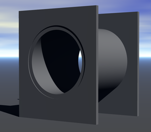
[[Image:cylinder-square-flange.png|thumb|3D View of Flange]] | |||
=Drawing= | =Drawing= | ||
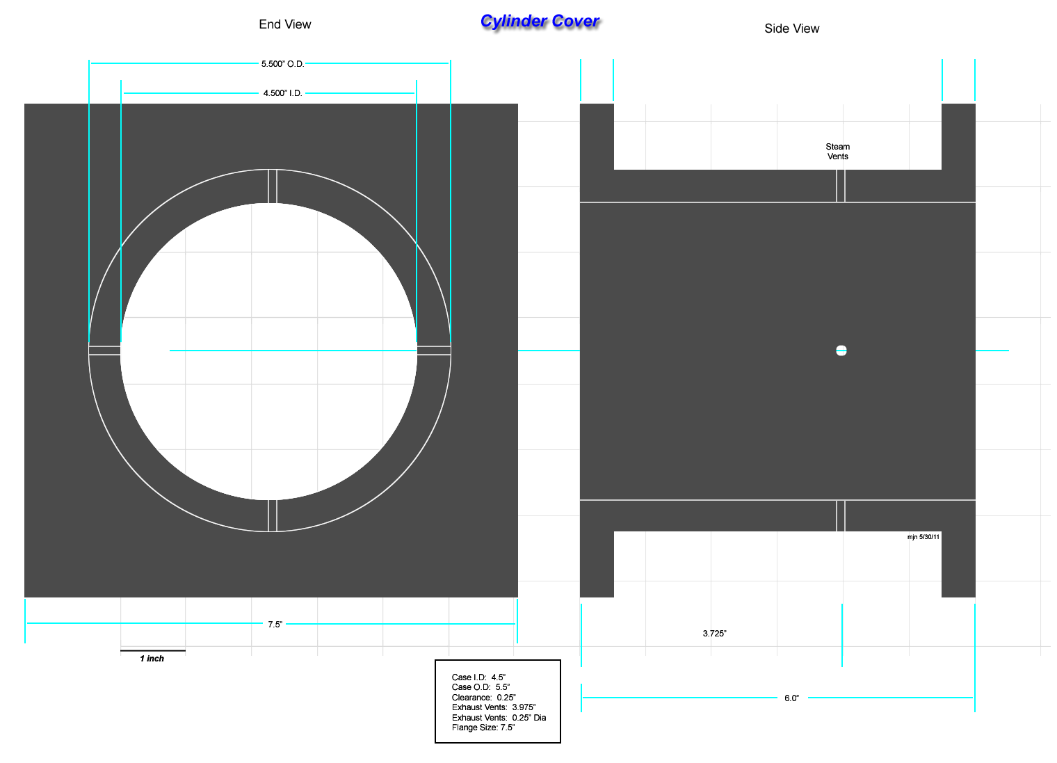
[[Image:Spec-Cylinder-Case2.png]] | [[Image:Spec-Cylinder-Case2.png]] | ||
=Instructions= | |||
'''Cylinder Case''' | |||
Use a cast iron pipe with an I.D of 4.5" and an O.D. of 5.5". | |||
# Mill a channel for the sensor vent 0.200" in at top for 1.00". | |||
# Drill a hole for the sensor vent at the end of the milled channel, 0.200" in diameter. | |||
# Drill four exhaust vent holes 3.725" from the top dead center end of the cylinder case at top, bottom, and both sides. | |||
'''Cylinder Flange''' | |||
Use half inch steel plate. | |||
# Cut a square 7.5" on a side. | |||
# Cut a circle of 5.5" diameter center in the square. | |||
# Make two. | |||
'''Cylinder Case Assembly''' | |||
# Weld the flanges one to each end of the cylinder case. | |||
# Grind welds flat on both ends. | |||
[[Category:Steam Engine]] | [[Category:Steam Engine]] | ||
Revision as of 14:26, 30 May 2011
Main > Energy > Steam Engine
Steam Engine Build Instructions
Description
The cylinder cover services to hold the cylinder liner in place and has two flanges that allow the valve assembly and mounting brackets to be attached.
There is some discussion at this time as to the shape of the cylinder flanges. Originally a circular shape was specified, but this complicates the fabrication process, especially in the valve cover since it calls for a cylindrical shape to be created and welded in place.
Positive Points for a Square Flange:
- Greatly simplifies construction
- Allows a cosmetic cover to be included later
Negative Aspects:
- Uses more metal
- Adds additional weight
- May require more bolts to fasten
Drawing
Instructions
Cylinder Case
Use a cast iron pipe with an I.D of 4.5" and an O.D. of 5.5".
- Mill a channel for the sensor vent 0.200" in at top for 1.00".
- Drill a hole for the sensor vent at the end of the milled channel, 0.200" in diameter.
- Drill four exhaust vent holes 3.725" from the top dead center end of the cylinder case at top, bottom, and both sides.
Cylinder Flange
Use half inch steel plate.
- Cut a square 7.5" on a side.
- Cut a circle of 5.5" diameter center in the square.
- Make two.
Cylinder Case Assembly
- Weld the flanges one to each end of the cylinder case.
- Grind welds flat on both ends.

