Steam Engine Build/Shaft: Difference between revisions
Jump to navigation
Jump to search
No edit summary |
mNo edit summary |
||
| Line 14: | Line 14: | ||
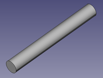
'''Drive Element'''<br> | '''Drive Element'''<br> | ||
[[Image:cad-crankshaft-drive-element.png] | [[Image:cad-crankshaft-drive-element.png]] | ||
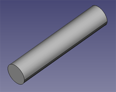
'''Crankshaft Element'''<br> | '''Crankshaft Element'''<br> | ||
[[Image:cad-crankshaft-crankshaft-element.png] | [[Image:cad-crankshaft-crankshaft-element.png]] | ||
Latest revision as of 17:21, 29 June 2011
Main > Energy > Steam Engine
Steam Engine Build Instructions
Description
The crankshaft is supported by two pillow block bearings and supports. In the single cylinder engine model it mates with a single crank arm. One end of the crank shaft is attached to a flywheel. The other end can be used for work output, such as driving an alternator or generator.
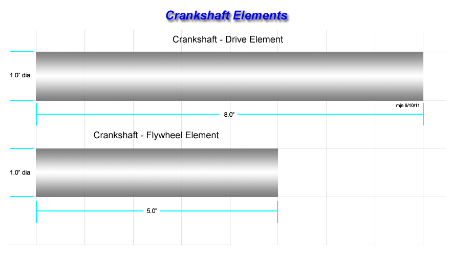
The crankshaft consists of two parts:
- Crankshaft drive element
- Crankshaft flywheel element
CAD
Drawing
Instructions
Cut two lengths of 1.0" diameter steel shaft:
- One with a length of 5.0"
- Second with a length of 8.0"
Neither of these lengths is critical and can be adjusted to whatever length is needed for a particular installation.


