Metal Roller: Difference between revisions
No edit summary |
No edit summary |
||
| Line 1: | Line 1: | ||
{{ToolTemplate|ToolName=Metal Roller}} | {{ToolTemplate|ToolName=Metal Roller}} | ||
[[ | [[File:GVCSToolpic.jpg|right|314px]] | ||
==Overview== | ==Overview== | ||
| Line 55: | Line 55: | ||
{{wanted|Versioning, milestones met, future goals}} | {{wanted|Versioning, milestones met, future goals}} | ||
[[Category:Metal Roller]] | |||
Revision as of 00:46, 21 August 2011
| Metal Roller | ||
|---|---|---|
| Home | Research & Development | Bill of Materials | Manufacturing Instructions | User's Manual | User Reviews | 
| |
Overview
The metal roller sends sheet metal and plate through gaps between cylinders to roll-bend them; this operation is used for producing cylindrical or conical components as well as wiring cylindrical edges.
insert video embed code here
Detailed Description
The metal roller is a universal "four-in-one" machine (meaning four cylinders to work with) that performs pinch rolling operations (lightly grips and moves sheet metal through the machine with a "free" roller to "set" the required bend radius) and pyramid rolling operations (moves plate metal through the machine to "set" the required bend radius). A hydraulically power-driven universal metal roller can be used for all required roll-bending operations.
Solution Statement
The metal roller allows the operator to perform roll-bending operations with ease.
Product Ecology
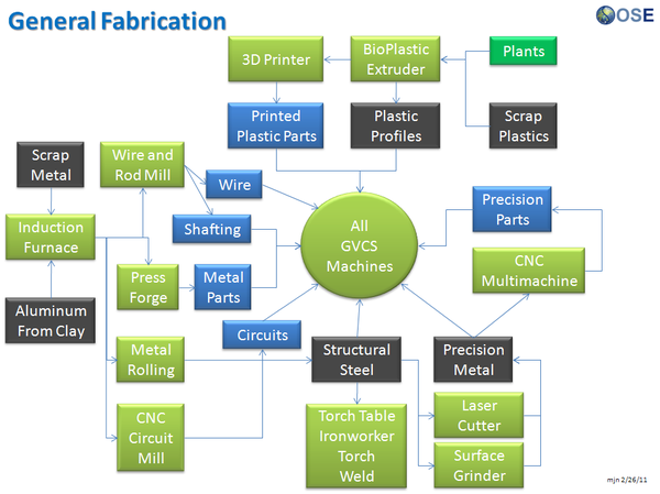
The metal roller fulfills the roll-bending role of metalworking operations in the GVCS. This ability is particularly useful for producing standard shapes of metal that would be time-consuming or impossible to form otherwise.
Components
The principal elements of the metal roller include:
- Frame: the ground-supported structure upon which the rest of the metal roller lies
- Couplers: the mechanisms that convert rotary motion from the hydraulic motor to the cylinders
- Hydraulic Circuit: the set of components that powers the hydraulic motor by sending pressurized fluid through its ports, hence producing rotary motion at the motor shaft
- Adjusters: the mechanisms that allow cylinder movement for different placement configurations on the plane perpendicular to the axis of rotation
- Cylinders: the components that make actual contact with the workpiece for roll-bending.
Specifications
| Spec | Value |
|---|---|
| Spec | Value |
OSE Project Status/Schedule
Wanted: Versioning, milestones met, future goals

