CEB Press/Manufacturing Instructions/Sensor Unit: Difference between revisions
Jump to navigation
Jump to search
No edit summary |
|||
| Line 34: | Line 34: | ||
[[Image:Cebpress-sensorunit-pourcompound.jpg|thumb]] | [[Image:Cebpress-sensorunit-pourcompound.jpg|thumb]] | ||
[[Image:sensorfab1.png|thumb|Step 1. Start with potting compound, 2 parts.]] | |||
[[Image:sensorfab2.png|Step 2. Take one Hall Effect sensor.]] | |||
Fabricate the Sensors | |||
#Cut three 3’ sections of Underground Telephone Cable. | |||
#Strip about 3” of the outer covering off each end of the three sections | |||
#Strip about ¼” off the orange, blue and blue-white wires at each end of each section. | |||
#Tin the ends of the all of the wires on all of the sections | |||
#Splice, with Solder, about 6” of the inner strands of some Cat-5 Cable (E17) to the wires at one end of each of the sections of Underground Telephone Cable | |||
#Thread shrink-wrap (E28) to the three wires on the other end of each of the three sections of Underground Telephone Cable. | |||
#Solder a Hall Effect Sensor (E20) to one endof the ther sections (pins numbered from left to right) | |||
##Pin 1: Orange | |||
##Pin 2: Blue-White | |||
##Pin 3: Blue | |||
#Shrink the Shrink-Wrap around each of the solder joints | |||
#Cut three 3” sections of PVC Pipe (E15). | |||
#Place a section of Pipe around each of the three hall effect sensors and encase them in Potting Compound (E29) with the Pipe Caps (E16) in place. | |||
Revision as of 06:07, 5 September 2011
Main > Housing and construction > CEB Press > CEB press building instructions
Tools Required
- solder iron
- heat gun
- wire cutter/stripper
- lighter
Materials Required
- hall effects sensor
- 1/2" poly pipe 5/8" o.d.
- underground telephone cable 4 wire
- potting compound
- disposable mixing cups
- tape
- cat5 cable
- shrink wrap
Diagrams
Fabrication Steps
- cut telephone cable 70" long
- strip shielding plastic 1.5" and 8" at either end
- solder hall effects sensor
Step 2. Take one Hall Effect sensor.
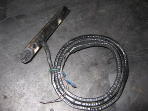
Fabricate the Sensors
- Cut three 3’ sections of Underground Telephone Cable.
- Strip about 3” of the outer covering off each end of the three sections
- Strip about ¼” off the orange, blue and blue-white wires at each end of each section.
- Tin the ends of the all of the wires on all of the sections
- Splice, with Solder, about 6” of the inner strands of some Cat-5 Cable (E17) to the wires at one end of each of the sections of Underground Telephone Cable
- Thread shrink-wrap (E28) to the three wires on the other end of each of the three sections of Underground Telephone Cable.
- Solder a Hall Effect Sensor (E20) to one endof the ther sections (pins numbered from left to right)
- Pin 1: Orange
- Pin 2: Blue-White
- Pin 3: Blue
- Shrink the Shrink-Wrap around each of the solder joints
- Cut three 3” sections of PVC Pipe (E15).
- Place a section of Pipe around each of the three hall effect sensors and encase them in Potting Compound (E29) with the Pipe Caps (E16) in place.


