Induction Furnace Conceptual Diagram: Difference between revisions
Jump to navigation
Jump to search
| Line 3: | Line 3: | ||
=Conceptual Diagram= | =Conceptual Diagram= | ||
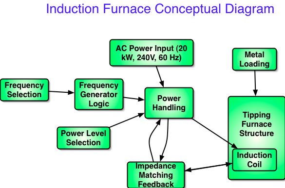
This is a conceptual diagram of the entire Induction Furnace system [[Image:induction_furnace.jpg]] from the [[Global Village Construction Set]]. The furnace is powered by 20 kW of 240VAC electricity from the [[LifeTrac]] generator. The entire system includes the power electronics, induction coil, and heating vessel - into which metal for melting is inserted: | This is a conceptual diagram of the entire Induction Furnace system [[Image:induction_furnace.jpg]] from the [[Global Village Construction Set]]. The furnace is powered by 20 kW of 240VAC electricity from the [[LifeTrac]] generator. The entire system includes the power electronics, induction coil, and heating vessel - into which metal for melting is inserted. This diagram intends to document the relationship of functional components in the induction furnace system, as a basis for technical development of components and their integration: | ||
[[Image:induction_concept.jpg]] | [[Image:induction_concept.jpg]] | ||
[[Category:Induction Furnace]] | [[Category:Induction Furnace]] | ||
Revision as of 16:34, 31 March 2009
See Metal_Melting_Furnace_Specifications for general application notes.
Conceptual Diagram
This is a conceptual diagram of the entire Induction Furnace system File:Induction furnace.jpg from the Global Village Construction Set. The furnace is powered by 20 kW of 240VAC electricity from the LifeTrac generator. The entire system includes the power electronics, induction coil, and heating vessel - into which metal for melting is inserted. This diagram intends to document the relationship of functional components in the induction furnace system, as a basis for technical development of components and their integration:
