Negligiblek's Pyrolysis Empirical Model: Difference between revisions
Negligiblek (talk | contribs) No edit summary |
Negligiblek (talk | contribs) |
||
| Line 77: | Line 77: | ||
=Test Run 00= | =Test Run 00= | ||
Thanks goes out to Danny Garcia and his son: their participation provided an indoors test during a small snow flurry, a laser thermometer to test temperature, and allowed for a quick change out of a leaking water basin. | |||
Stock: .17 lbs dry white pine .17 lbs | |||
Water basin had to be replaced as it had a leak. | |||
SD memory left in laptop at home, only 10 pictures inside camera's memory: no cable to download from camera. | |||
Left 1/4 turn valve closed in hopes gas would compress in water basin, then cool in cooling coil. Did not want gas to escape into enclosed area as this gas could be five parts H2. | |||
Modeling clay sealed around the water basin lid openings of the cooling coil and the gas output pipe. | |||
Far left branch of loop 5 degrees cooler than far right branch of loop: implies circulation in a counterclockwise direction. The loop of the pyrolysis chamber ran about 70 to 75 degrees F in an ambient temperature of about 59 to 61 degrees F. | |||
Heated up burn chamber to around 340 degrees F before silver solder would begin to melt, then let cool down to about 130 degrees. Did this cycle five times. | |||
Clearly heard gas bubbling. Upon the cooling process, clearly heard water draining in pyrolysis device. | |||
After unsealing pyrolysis chamber, found that water had been forced back into the pyrolysis burn chamber. | |||
Very little of the wood had burned. | |||
Wood was dry to the touch. | |||
Found flamable oil collected on steel cap. | |||
Water turned a very light brown and left ring around water basin wall. | |||
Poured all water into water basin, will let set over night in hope oil will collect on top of water. | |||
Weighed the wood again: .16 lbs | |||
=Things learned from Test Run 00= | |||
[[Category:Pyrolysis Oil]] | [[Category:Pyrolysis Oil]] | ||
Revision as of 00:13, 5 April 2009
Model for Empirical Knowledge
I have zero experience with pyrolysis. Since Marcin asked me to lead this project, I realized I'd need to know what I was talking about when I attempted to lure and retain more experienced Pyrolysis Collaborators.
I did not study anything or look at many designs before I began. I simply wanted to build a model and see what issues arise which others have experienced but don't really list in their experimental findings. Nor did I do any calculations of any sort. I winged it. If it blows up on me, I'll do more homework (call me Sir Francis as in Bacon: hopefully not burnt bacon).
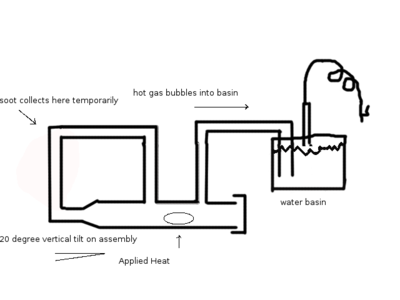
Unscaled Drawing of Model
The overall conceptual goal is to get oil out of the cooling coils on the right side after inserting a biomass where the elliptical shape is in the pipe, sealing the pipe with teflon tape and a threaded cap, and heating the pipe directly under the biomass with MAPP gas for an undetermined amount of time.
The loop on the left side is a crude attempt at trying to trap soot for further burning by inclining the model 20 degrees on the left side. Should the gases ever reach laminar flow, convection along with laminar flow fluid dymanics: AV=AV (where A=cross sectional area the flow passes through, and V=the velocity of the fluid), may cause circulation in the loop.
If soot and cinder stay mostly to the left, then the outlet for the gases and the water in the water basin should stay cleaner.
The pressure inside the combustion chamber should be equal to the height of the column of water the outlet pipe is submerged under (15cm).
Density of tap water at 20 deg C: .99823 g/cm3 or 998.23kg/m3 Pressure=density*g*h= (998.23kg/m3)*(9.81m/s2)*.15m = 1468.895445 Pa (kg/m*s2) or about 0.213 psi over and above atmospheric pressure.
Photos of Manufacture and Assembly
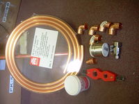
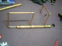
Partial Collection of Parts March 21st, 2009
Missing from the parts above are:
- 1' 2" dia copper pipe length;
- 2" Cap, 2" Screw Cap;
- Unknown copper pipe length for feed back loop
- Water basin
- Water basin lid
- Water basin lid gasket
Not shown in pictures is the MAPP gas canister and torch head.
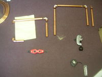
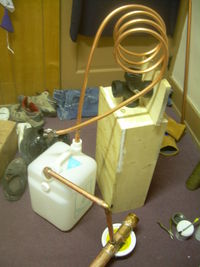
- The two right most vertical pipes will go through the water basin lid.
- The right most vertical pipe will be inside the water basin but not submerged in water and will have 10' of 1/2" copper tubing on the top end.
- The other end of the 1/2" copper tubing will terminate in the 1/4 turn shut off valve.
- On the far left side of the picture, one vertical pipe is missing; hence the hanging elbow.
- The next two left most (and present) vertical parts will connect into the missing 1' x 2" dia. copper pipe
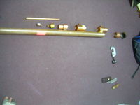
March 29th, 2009 Obtained the following parts:
- 36" of 2" dia copper pipe
- Two 2" to 3/4" tees
- 2" to 1.5" coupler
- 1.5" to 1/2" coupler
- 5' of 1/2" copper pipe
- 1/2" to 3/4" coupler
- 2" copper threaded end
- steel cap
- teflon tape
Obviously, these are not the parts I had intended. Being in a hurry, I made do with what the hardware store had in supply.
March 29th, 2009 Assembled All parts with the exception of:
- water basin
- water basin lid
- Did not solder cooling tube to outlet
- Did not crimp 1/4 turn valve on to cooling tube
No, the soldering doesn't look pretty and I didn't try to clean it up before I shot it either. It does hold air though. The hunt for a good water basin continues.
April 3rd, 2009 Obtained Water Basin, and Modeling clay to seal Water Basin.
Planned test burn for April 4th (one day ahead of promised date)!
Test Run 00
Thanks goes out to Danny Garcia and his son: their participation provided an indoors test during a small snow flurry, a laser thermometer to test temperature, and allowed for a quick change out of a leaking water basin.
Stock: .17 lbs dry white pine .17 lbs
Water basin had to be replaced as it had a leak.
SD memory left in laptop at home, only 10 pictures inside camera's memory: no cable to download from camera.
Left 1/4 turn valve closed in hopes gas would compress in water basin, then cool in cooling coil. Did not want gas to escape into enclosed area as this gas could be five parts H2.
Modeling clay sealed around the water basin lid openings of the cooling coil and the gas output pipe.
Far left branch of loop 5 degrees cooler than far right branch of loop: implies circulation in a counterclockwise direction. The loop of the pyrolysis chamber ran about 70 to 75 degrees F in an ambient temperature of about 59 to 61 degrees F.
Heated up burn chamber to around 340 degrees F before silver solder would begin to melt, then let cool down to about 130 degrees. Did this cycle five times.
Clearly heard gas bubbling. Upon the cooling process, clearly heard water draining in pyrolysis device.
After unsealing pyrolysis chamber, found that water had been forced back into the pyrolysis burn chamber.
Very little of the wood had burned.
Wood was dry to the touch.
Found flamable oil collected on steel cap.
Water turned a very light brown and left ring around water basin wall.
Poured all water into water basin, will let set over night in hope oil will collect on top of water.
Weighed the wood again: .16 lbs
