RepRap Build: Difference between revisions
No edit summary |
|||
| Line 110: | Line 110: | ||
#Procuring rod and stud - and cutting to length. | #Procuring rod and stud - and cutting to length. | ||
=Steps taken by Peter Koeleman= | |||
To assist Factor-e-Farm building their reprap machine, I'm building a Mendel model. So far I ordered the needed generation 3 hardware and soldered up some parts that didn't come prefab. I'm using 'off the shelf' hardware that doesn't need a lot of work to make life easier and to avoid mistakes. | |||
Here are videos of the progress. | |||
<html> | |||
<iframe src="https://player.vimeo.com/video/14302176" width="400" height="300" frameborder="0"></iframe><p><a href="http://vimeo.com/14302176">Testing RepRap motherboard</a> from <a href="http://vimeo.com/user3358588">Peter Koeleman</a> on <a href="http://vimeo.com">Vimeo</a>.</p><p>I hooked up the RepRap motherboard from grrf.de to an ATX powersupply and an UM232R chip to the serial interface.<br /> | |||
Running the reprap software with CommsDebug set to true continuously dumps information on the console.</p> | |||
<iframe src="https://player.vimeo.com/video/14303485" width="400" height="300" frameborder="0"></iframe><p><a href="http://vimeo.com/14303485">Testing RepRap motherboard and extruder board</a> from <a href="http://vimeo.com/user3358588">Peter Koeleman</a> on <a href="http://vimeo.com">Vimeo</a>.</p><p>I hooked up the extruder controller board to the motherboard and ran the reprap software again with CommsDebug on. Note the T:2 value which was T:0 before when the motherboard couldn't read the (bogus) temperature value yet.</p> | |||
</html> | |||
I have ordered stepper motors and a load of nuts and bolts. When I get those I will be able to test the stepper motor boards. Then I need to start constructing the frame. For this we think it might be doable that I help finish the Darwin model from Factor-e-Farm first to get the printed parts. | |||
The last step will be to construct an extra Mendel machine for Factor-e-Farm because with self replicating hardware it's a good idea to have a spare. | |||
[[Category:RepRap]] | [[Category:RepRap]] | ||
Revision as of 13:12, 21 August 2010
Parts
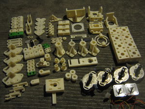
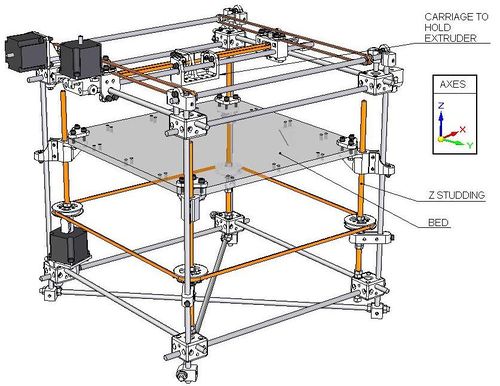
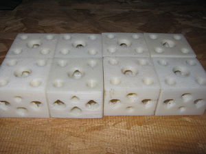
- Frame corners and rods - using 5/16" rod and threaded rod (studs in British)
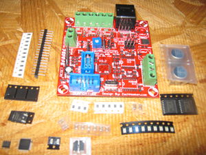
- Extruder controller - [1]
- [3] Nema 17 motors: 2 for x and y axes, and 1 for extruder - [2]
Frame Rod and Threaded Rod
This work is based on the RepRap master BOM. Its metric system is adapted to retarded Imperial units. We are using 5/16" stock instead of M8.
- xy spacer rod - [1] 355 mm or
- x idler rod - [1] 40 mm
- x motor bracket rod - [2] 520 mm
- xy frame rod - [8] 500 mm
- studding idler studs - [3] 384 mm
- studding drive stud - [1] 260 mm
- vertical post rods - [3] 500 mm
- vertical post rod - [1] 465 mm
- Z axis drive - [4] 275 mm, stainless recommended for straightness and smoothness by HydraRaptor
- base diagonal studs - [2] 660 mm
- Note: All diagonals are studs because they have nuts on ends
- y bearing housing rod - [3] 70 mm
- y idler rod - [1] 472 mm or
- y drive rod - [1] 452 mm or
- side diagonal studs - [8] 660 mm or
- nuts - [32]
- washers - [32]
- M5x8 mm or .20 x .31 in (see Metric to Inch Conversion)
Tools
- Tweezers for surface mount component handling.
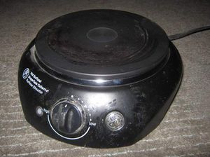
- Hot plate
Assembly
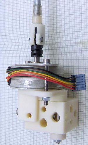
- $8 z axis
- Start with mechanical assembly from RepRap wiki
Notes
On Frame Rods
From Erik:
As long as they're about 8mm in diameter you're good. Everything is designed such that tight tolerances are not required. Part of assembling a machine is taking a series of measurement. You can get away with threaded rods for most of the structural parts, except for the elements that other parts should be able to slide over. Several parts of the frame double as a guide for an axis.
You can also use cheap rod for most of the frame, the sliding ones should be maximally stiff (hardened rod) and chrome coated is nice and shiny. I'm using only the cheap type of ground bars for my own second Darwin, currently. It works fine. You don't need a heavy CNC grade frame when doing additive manufacturing, it's just very inefficient.
On Parts Choices
From Chris Palmer:
We are planning on using the parts shown, including your $8 z axis.
Are the Mother Board v1.1 and Extruder Controller v2.2 the correct boards to use?
The motherboard has moved on to 1.2, but I think the changes are very minor, so 1.1 should work fine. Extruder controller V2.2 is current. You will also need three stepper motor drivers of course.
What do you recommend for the implementation of the extruder?
I would recommend Wade's design: http://reprap.org/wiki/Geared_Nema17_Extruder. You will probably need to make an adapter plate to mount in on the Darwin carriage, but that should be trivial.
You can either bootstrap using the extruder parts I sent you and then print Wade's or I can print you a set of parts for Wade's if you don't want the hassle.
You can make the standard hot end if you have a lathe, but I would recommend the PEEK / PTFE Hybrid from Brian Reifsnider. http://hydraraptor.blogspot.com/2010/05/plumbstruder.html He sells in the forums and on eBay for very reasonable prices.
I see you're selling Mendel parts on Ebay. Is Mendel achieving widespread replicability?
It hasn't achieved the utopian ideal of everybody printing two sets and passing them on for cost yet, but there are a lot more people printing them than ever printed a Darwin. I have printed about 20 sets since April and got prices from £226 to £460 on eBay. A lot of people have printed their own using Makerbots and Rapmans, so I think there will be 100's around already. The eBay prices provide strong motivation for people to print parts and I am staring to see competition driving the prices down.
From Erik de Bruijn
The latest versions of these boards are fine. Older versions tend to have more users so you'll also find many solutions compatible to these boards (firmware).
You don't need the extruder controller per se, a TIP110 will do (two integrated transistors to control a bigger current from a chip's I/O pins), but the extruder board probably makes life easier (I just use one controller running 4 steppers and temp. control, but there's no reasons to do this if you have all the parts).
> What do you recommend for the implementation of the extruder?
Many people use Wade's extruder (also based on Adrian Bowyers work). It now contains improvements by Nophead too. http://www.thingiverse.com/thing:3462 However it seems you have a direct drive version for a NEMA17 motor. This one is fine to bootstrap Wade/nophead's extruder with. The direct drive version is very good because of its simplicity. If it works it won't break or wear out. It has few parts, don't need to source exotic things. Though it might lack the torque for really fast printing. You can also adapt it to fit a NEMA23 motor by drilling a small sheet of material with the holes, similar to this printed part. Wade's extruder uses a big bolt as a pinch wheel, that also should work pretty well. You can also see if makerbot's newer pinch-wheels will fit the diameter of your motors. Though I'm not sure whether it will fit your direct drive extruder bracket (it has a pretty big boss/hub).
On Frame Structure Lengths
Q. I will read the build instructions and try to figure out these inconsistencies. I imagine I could make it work by making adjustments. Is it safe to make changes in the structure, or is the design shown typically followed exactly?
A. You could change the frame size but you would have to get the table size correct to match, so it would be easiest to make it the correct size. You can change the height pretty easily though.
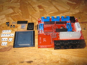
Q Also, on the SMT electronics attachment - I received the motherboard with the plastic parts already attached, but the SMT components are not yet attached. Do I need to take the plastic parts off, as they will fry upon heating? I have a spare motherboard PCB, so starting from scratch is not too bad.
A. Certainly you need to remove them if you plan to use a reflow with an oven or plate as they will probably melt. You could see what happens and replace them afterwards if you have spares. Also the PCB won't sit flat on a plate with the through hole pins on the back, so won't get proper thermal contact.
A. You could hand solder the SMT parts if you can get to them with the iron. Weird to put the connectors on first. Even with through hole assembly you put the large items on last, so you can get to the small ones.
Q. I have this heater plate, 1000W. Is this ok?
A. A lot of people use such things. I think you will struggle to follow the correct solder profile with it, but then a lot of hobbyists ignore that and get away with it. A local reprapper even re-flowed them in a frying pan over a gas ring! I think one board didn't work and she had to replace some of the chips though.
Steps taken at Factor e Farm
- Procuring rod and stud - and cutting to length.
Steps taken by Peter Koeleman
To assist Factor-e-Farm building their reprap machine, I'm building a Mendel model. So far I ordered the needed generation 3 hardware and soldered up some parts that didn't come prefab. I'm using 'off the shelf' hardware that doesn't need a lot of work to make life easier and to avoid mistakes.
Here are videos of the progress.
Testing RepRap motherboard from Peter Koeleman on Vimeo.
I hooked up the RepRap motherboard from grrf.de to an ATX powersupply and an UM232R chip to the serial interface.
Running the reprap software with CommsDebug set to true continuously dumps information on the console.
Testing RepRap motherboard and extruder board from Peter Koeleman on Vimeo.
I hooked up the extruder controller board to the motherboard and ran the reprap software again with CommsDebug on. Note the T:2 value which was T:0 before when the motherboard couldn't read the (bogus) temperature value yet.
I have ordered stepper motors and a load of nuts and bolts. When I get those I will be able to test the stepper motor boards. Then I need to start constructing the frame. For this we think it might be doable that I help finish the Darwin model from Factor-e-Farm first to get the printed parts.
The last step will be to construct an extra Mendel machine for Factor-e-Farm because with self replicating hardware it's a good idea to have a spare.
