Tobbens Folgertech Kit Assembly Log: Difference between revisions
m (→Log) |
(→Log) |
||
| Line 30: | Line 30: | ||
|Bottom Frame 1 | |Bottom Frame 1 | ||
|Removing tape from 2020s | |Removing tape from 2020s | ||
| | |0:05:46 | ||
|0:05:46 | |0:05:46 | ||
|None | |None | ||
| Line 39: | Line 39: | ||
|Bottom Frame 2 | |Bottom Frame 2 | ||
|Identifying which beams to use | |Identifying which beams to use | ||
| | |0:04:55 | ||
|0:10:41 | |0:10:41 | ||
|[https://drive.google.com/folderview?id=0B9b1NbuMK524fldIWWVCa0xfSXAtZmttcDhrbjBMeFNWcENBdVUzWnhtWDZ2YWdHVXpoUXM&usp=drive_web Folgertech's Build Manual] | |[https://drive.google.com/folderview?id=0B9b1NbuMK524fldIWWVCa0xfSXAtZmttcDhrbjBMeFNWcENBdVUzWnhtWDZ2YWdHVXpoUXM&usp=drive_web Folgertech's Build Manual] | ||
| Line 48: | Line 48: | ||
|Bottom Frame 3 | |Bottom Frame 3 | ||
|Watching Module 1 Video | |Watching Module 1 Video | ||
| | |0:01:30 | ||
|0:12:11 | |0:12:11 | ||
|[https://www.youtube.com/watch?v=JGs9slUxVe0 module 1 video] | |[https://www.youtube.com/watch?v=JGs9slUxVe0 module 1 video] | ||
| Line 57: | Line 57: | ||
|Bottom Frame 4 | |Bottom Frame 4 | ||
|Very roughly sorting Hardware Bag contents | |Very roughly sorting Hardware Bag contents | ||
| | |0:02:20 | ||
|0:14:31 | |0:14:31 | ||
| | | | ||
| Line 66: | Line 66: | ||
|Bottom Frame 5 | |Bottom Frame 5 | ||
|Assembly of 8 first L-brackets | |Assembly of 8 first L-brackets | ||
|16:01 | |0:16:01 | ||
|0:30:32 | |0:30:32 | ||
|[https://www.youtube.com/watch?v=JGs9slUxVe0 module 1 video] | |[https://www.youtube.com/watch?v=JGs9slUxVe0 module 1 video] | ||
| Line 75: | Line 75: | ||
|Bottom Frame 6 | |Bottom Frame 6 | ||
|Confusion regarding the T-nut and screw sizes. | |Confusion regarding the T-nut and screw sizes. | ||
|16:54 | |0:16:54 | ||
|0:47:26 | |0:47:26 | ||
|[https://www.youtube.com/watch?v=JGs9slUxVe0 module 1 video], [https://drive.google.com/folderview?id=0B9b1NbuMK524fldIWWVCa0xfSXAtZmttcDhrbjBMeFNWcENBdVUzWnhtWDZ2YWdHVXpoUXM&usp=drive_web Folgertech's Build Manual] | |[https://www.youtube.com/watch?v=JGs9slUxVe0 module 1 video], [https://drive.google.com/folderview?id=0B9b1NbuMK524fldIWWVCa0xfSXAtZmttcDhrbjBMeFNWcENBdVUzWnhtWDZ2YWdHVXpoUXM&usp=drive_web Folgertech's Build Manual] | ||
| Line 84: | Line 84: | ||
|Bottom Frame 7 | |Bottom Frame 7 | ||
|Assembly of left Y-rod bushings and corner brackets in middle of front beam | |Assembly of left Y-rod bushings and corner brackets in middle of front beam | ||
| | |0:09:01 | ||
|0:56:27 | |0:56:27 | ||
|[https://www.youtube.com/watch?v=JGs9slUxVe0 module 1 video] | |[https://www.youtube.com/watch?v=JGs9slUxVe0 module 1 video] | ||
| Line 93: | Line 93: | ||
|Vertical Frame 1 | |Vertical Frame 1 | ||
|Assembly and Mounting on Base Frame | |Assembly and Mounting on Base Frame | ||
|33:33 | |0:33:33 | ||
|1:30:00 | |1:30:00 | ||
|[https://www.youtube.com/watch?v=JGs9slUxVe0 module 1 video] | |[https://www.youtube.com/watch?v=JGs9slUxVe0 module 1 video] | ||
| Line 102: | Line 102: | ||
|X-axis 1 | |X-axis 1 | ||
|Faulty Assembly of X-carriage Linear Bearings | |Faulty Assembly of X-carriage Linear Bearings | ||
| | |0:09:41 | ||
|1:39:41 | |1:39:41 | ||
|[https://www.youtube.com/watch?v=_-Ll_-x1woM module 2 video] | |[https://www.youtube.com/watch?v=_-Ll_-x1woM module 2 video] | ||
| Line 111: | Line 111: | ||
|X-axis 2 | |X-axis 2 | ||
|Faulty Assembly of X-carriage Linear Bearings 2 | |Faulty Assembly of X-carriage Linear Bearings 2 | ||
|10:25 | |0:10:25 | ||
|1:50:06 | |1:50:06 | ||
| | | | ||
| Line 120: | Line 120: | ||
|X-axis 3 | |X-axis 3 | ||
|Assembly of X-carriage Linear Bearings | |Assembly of X-carriage Linear Bearings | ||
| | |0:04:59 | ||
|1:55:05 | |1:55:05 | ||
| | | | ||
| Line 129: | Line 129: | ||
|X-axis 4 | |X-axis 4 | ||
|Mount Linear Bearings Into X-idlers | |Mount Linear Bearings Into X-idlers | ||
| | |0:03:02 | ||
|1:58:07 | |1:58:07 | ||
|[https://www.youtube.com/watch?v=_-Ll_-x1woM module 2 video] | |[https://www.youtube.com/watch?v=_-Ll_-x1woM module 2 video] | ||
| Line 138: | Line 138: | ||
|X-axis 5 | |X-axis 5 | ||
|Mounting X idler bearings | |Mounting X idler bearings | ||
| | |0:02:47 | ||
|2:0:54 | |2:0:54 | ||
|[https://www.youtube.com/watch?v=_-Ll_-x1woM module 2 video] | |[https://www.youtube.com/watch?v=_-Ll_-x1woM module 2 video] | ||
| Line 147: | Line 147: | ||
|X-axis 6 | |X-axis 6 | ||
|Mounting X Belt pulley and X-motor | |Mounting X Belt pulley and X-motor | ||
| | |0:08:43 | ||
|2:9:37 | |2:9:37 | ||
|[https://www.youtube.com/watch?v=_-Ll_-x1woM module 2 video] | |[https://www.youtube.com/watch?v=_-Ll_-x1woM module 2 video] | ||
| Line 156: | Line 156: | ||
|X-axis 7 | |X-axis 7 | ||
|Fitting together idlers, carriage and linear rods | |Fitting together idlers, carriage and linear rods | ||
| | |0:01:48 | ||
|2:11:25 | |2:11:25 | ||
|[https://www.youtube.com/watch?v=_-Ll_-x1woM module 2 video] | |[https://www.youtube.com/watch?v=_-Ll_-x1woM module 2 video] | ||
| Line 165: | Line 165: | ||
|X-axis 8 | |X-axis 8 | ||
|Thread X-belt | |Thread X-belt | ||
| | |0:04:29 | ||
|2:15:54 | |2:15:54 | ||
|[https://www.youtube.com/watch?v=_-Ll_-x1woM module 2 video] | |[https://www.youtube.com/watch?v=_-Ll_-x1woM module 2 video] | ||
| Line 174: | Line 174: | ||
|Z-axis 1 | |Z-axis 1 | ||
|Preparing Z-motors | |Preparing Z-motors | ||
| | |0:06:50 | ||
|2:22:44 | |2:22:44 | ||
|[https://www.youtube.com/watch?v=QE-ueNbo4iU module 3 video] | |[https://www.youtube.com/watch?v=QE-ueNbo4iU module 3 video] | ||
| Line 183: | Line 183: | ||
|Z-axis 2 | |Z-axis 2 | ||
|Preparing filament guide | |Preparing filament guide | ||
| | |0:02:03 | ||
|2:24:47 | |2:24:47 | ||
|[https://www.youtube.com/watch?v=QE-ueNbo4iU module 3 video] | |[https://www.youtube.com/watch?v=QE-ueNbo4iU module 3 video] | ||
| Line 192: | Line 192: | ||
|Z-axis 3 | |Z-axis 3 | ||
|Preparing Z-motors' T-nuts | |Preparing Z-motors' T-nuts | ||
| | |0:03:14 | ||
|2:28:01 | |2:28:01 | ||
|[https://www.youtube.com/watch?v=QE-ueNbo4iU module 3 video] | |[https://www.youtube.com/watch?v=QE-ueNbo4iU module 3 video] | ||
| Line 201: | Line 201: | ||
|Y-axis 1 | |Y-axis 1 | ||
|Manually Enlargening Linear Bearing Holders | |Manually Enlargening Linear Bearing Holders | ||
|13:20 | |0:13:20 | ||
|2:41:20 | |2:41:20 | ||
| | | | ||
| Line 210: | Line 210: | ||
|Y-axis 2 | |Y-axis 2 | ||
|Threading zip-ties and figuring out how to place printed bearing holders | |Threading zip-ties and figuring out how to place printed bearing holders | ||
| | |0:04:39 | ||
|2:45:59 | |2:45:59 | ||
|[https://drive.google.com/folderview?id=0B9b1NbuMK524fldIWWVCa0xfSXAtZmttcDhrbjBMeFNWcENBdVUzWnhtWDZ2YWdHVXpoUXM&usp=drive_web Folgertech Build Manual] | |[https://drive.google.com/folderview?id=0B9b1NbuMK524fldIWWVCa0xfSXAtZmttcDhrbjBMeFNWcENBdVUzWnhtWDZ2YWdHVXpoUXM&usp=drive_web Folgertech Build Manual] | ||
| Line 219: | Line 219: | ||
|Y-axis 3 | |Y-axis 3 | ||
|Drilling out printed bearing holders' 3mm holes | |Drilling out printed bearing holders' 3mm holes | ||
| | |0:04:59 | ||
|2:50:58 | |2:50:58 | ||
| | | | ||
| Line 228: | Line 228: | ||
|Y-axis 4 | |Y-axis 4 | ||
|Fastening Y Linear Bearings | |Fastening Y Linear Bearings | ||
| | |0:09:47 | ||
|3:0:52 | |3:0:52 | ||
|[https://drive.google.com/folderview?id=0B9b1NbuMK524fldIWWVCa0xfSXAtZmttcDhrbjBMeFNWcENBdVUzWnhtWDZ2YWdHVXpoUXM&usp=drive_web Folgertech Build Manual] page 8 | |[https://drive.google.com/folderview?id=0B9b1NbuMK524fldIWWVCa0xfSXAtZmttcDhrbjBMeFNWcENBdVUzWnhtWDZ2YWdHVXpoUXM&usp=drive_web Folgertech Build Manual] page 8 | ||
| Line 237: | Line 237: | ||
|Y-axis 5 | |Y-axis 5 | ||
|Soldering and taping heat bed wires | |Soldering and taping heat bed wires | ||
|29:50 | |0:29:50 | ||
|3:30:42 | |3:30:42 | ||
|[https://drive.google.com/folderview?id=0B9b1NbuMK524fldIWWVCa0xfSXAtZmttcDhrbjBMeFNWcENBdVUzWnhtWDZ2YWdHVXpoUXM&usp=drive_web Folgertech Build Manual] pages 9, 10 and 11 | |[https://drive.google.com/folderview?id=0B9b1NbuMK524fldIWWVCa0xfSXAtZmttcDhrbjBMeFNWcENBdVUzWnhtWDZ2YWdHVXpoUXM&usp=drive_web Folgertech Build Manual] pages 9, 10 and 11 | ||
| Line 246: | Line 246: | ||
|Y-axis 6 | |Y-axis 6 | ||
|Mounting Heat Bed onto Y-Carriage | |Mounting Heat Bed onto Y-Carriage | ||
| | |0:05:40 | ||
|3:36:30 | |3:36:30 | ||
|[https://drive.google.com/folderview?id=0B9b1NbuMK524fldIWWVCa0xfSXAtZmttcDhrbjBMeFNWcENBdVUzWnhtWDZ2YWdHVXpoUXM&usp=drive_web Folgertech Build Manual] page 11 | |[https://drive.google.com/folderview?id=0B9b1NbuMK524fldIWWVCa0xfSXAtZmttcDhrbjBMeFNWcENBdVUzWnhtWDZ2YWdHVXpoUXM&usp=drive_web Folgertech Build Manual] page 11 | ||
| Line 255: | Line 255: | ||
|Y-axis and Frame 1 | |Y-axis and Frame 1 | ||
|Mount Y-motor mount | |Mount Y-motor mount | ||
| | |0:02:54 | ||
|3:39:24 | |3:39:24 | ||
|[https://drive.google.com/folderview?id=0B9b1NbuMK524fldIWWVCa0xfSXAtZmttcDhrbjBMeFNWcENBdVUzWnhtWDZ2YWdHVXpoUXM&usp=drive_web Folgertech Build Manual] page 4 | |[https://drive.google.com/folderview?id=0B9b1NbuMK524fldIWWVCa0xfSXAtZmttcDhrbjBMeFNWcENBdVUzWnhtWDZ2YWdHVXpoUXM&usp=drive_web Folgertech Build Manual] page 4 | ||
| Line 264: | Line 264: | ||
|Y-axis and Frame 2 | |Y-axis and Frame 2 | ||
|Mounting Y-Carriage | |Mounting Y-Carriage | ||
|10:40 | |0:10:40 | ||
|3:50:04 | |3:50:04 | ||
| | | | ||
| Line 273: | Line 273: | ||
|Y-axis and Frame 3 | |Y-axis and Frame 3 | ||
|Mounting Y-motor | |Mounting Y-motor | ||
| | |0:05:29 | ||
|3:55:33 | |3:55:33 | ||
| | | | ||
| Line 282: | Line 282: | ||
|Y-axis and Frame 4 | |Y-axis and Frame 4 | ||
|Assembling Y-idler | |Assembling Y-idler | ||
|20:51 | |0:20:51 | ||
|4:16:24 | |4:16:24 | ||
|[https://drive.google.com/folderview?id=0B9b1NbuMK524fldIWWVCa0xfSXAtZmttcDhrbjBMeFNWcENBdVUzWnhtWDZ2YWdHVXpoUXM&usp=drive_web Folgertech Build Manual] page 20 | |[https://drive.google.com/folderview?id=0B9b1NbuMK524fldIWWVCa0xfSXAtZmttcDhrbjBMeFNWcENBdVUzWnhtWDZ2YWdHVXpoUXM&usp=drive_web Folgertech Build Manual] page 20 | ||
| Line 291: | Line 291: | ||
|Y-axis and Frame 5 | |Y-axis and Frame 5 | ||
|Threading Y-belt | |Threading Y-belt | ||
| | |0:04:37 | ||
|4:21:01 | |4:21:01 | ||
| | | | ||
| Line 300: | Line 300: | ||
|X-axis, Z-axis and Frame 1 | |X-axis, Z-axis and Frame 1 | ||
|Shortening X-axis and Pushing it in place | |Shortening X-axis and Pushing it in place | ||
| | |0:07:30 | ||
|4:28:31 | |4:28:31 | ||
| | | | ||
| Line 309: | Line 309: | ||
|X-axis, Z-axis and Frame 2 | |X-axis, Z-axis and Frame 2 | ||
|Tightening X-belt and right Z-rod bushing screw | |Tightening X-belt and right Z-rod bushing screw | ||
| | |0:03:30 | ||
|4:32:01 | |4:32:01 | ||
| | | | ||
| Line 318: | Line 318: | ||
|X-axis, Z-axis and Frame 3 | |X-axis, Z-axis and Frame 3 | ||
|Mount left Z-motor | |Mount left Z-motor | ||
| | |0:05:44 | ||
|4:37:45 | |4:37:45 | ||
| | | | ||
| Line 327: | Line 327: | ||
|X-axis, Z-axis and Frame 4 | |X-axis, Z-axis and Frame 4 | ||
|Mount Right Z-motor | |Mount Right Z-motor | ||
| | |0:06:34 | ||
|4:44:19 | |4:44:19 | ||
| | | | ||
| Line 336: | Line 336: | ||
|X-axis and Extruder 1 | |X-axis and Extruder 1 | ||
|Mount Extruder | |Mount Extruder | ||
| | |0:09:26 | ||
|4:53:45 | |4:53:45 | ||
|[https://drive.google.com/folderview?id=0B9b1NbuMK524fldIWWVCa0xfSXAtZmttcDhrbjBMeFNWcENBdVUzWnhtWDZ2YWdHVXpoUXM&usp=drive_web Folgertech Build Manual] pages 18 and 19 | |[https://drive.google.com/folderview?id=0B9b1NbuMK524fldIWWVCa0xfSXAtZmttcDhrbjBMeFNWcENBdVUzWnhtWDZ2YWdHVXpoUXM&usp=drive_web Folgertech Build Manual] pages 18 and 19 | ||
| Line 345: | Line 345: | ||
|Endstop sensors and Frame 1 | |Endstop sensors and Frame 1 | ||
|Mounting endstops | |Mounting endstops | ||
|23:03 | |0:23:03 | ||
|5:16:48 | |5:16:48 | ||
|[https://drive.google.com/folderview?id=0B9b1NbuMK524fldIWWVCa0xfSXAtZmttcDhrbjBMeFNWcENBdVUzWnhtWDZ2YWdHVXpoUXM&usp=drive_web Folgertech Build Manual] pages 32 and 33 | |[https://drive.google.com/folderview?id=0B9b1NbuMK524fldIWWVCa0xfSXAtZmttcDhrbjBMeFNWcENBdVUzWnhtWDZ2YWdHVXpoUXM&usp=drive_web Folgertech Build Manual] pages 32 and 33 | ||
| Line 354: | Line 354: | ||
|Electronics 01 | |Electronics 01 | ||
|Re-Mounting Power Supply | |Re-Mounting Power Supply | ||
| | |0:03:42 | ||
|5:20:30 | |5:20:30 | ||
| | | | ||
| Line 363: | Line 363: | ||
|Electronics 02 | |Electronics 02 | ||
|Attach mains voltage | |Attach mains voltage | ||
|14:44 | |0:14:44 | ||
|5:31:32 | |5:31:32 | ||
|[https://drive.google.com/folderview?id=0B9b1NbuMK524fldIWWVCa0xfSXAtZmttcDhrbjBMeFNWcENBdVUzWnhtWDZ2YWdHVXpoUXM&usp=drive_web Folgertech Build Manual] page 35 | |[https://drive.google.com/folderview?id=0B9b1NbuMK524fldIWWVCa0xfSXAtZmttcDhrbjBMeFNWcENBdVUzWnhtWDZ2YWdHVXpoUXM&usp=drive_web Folgertech Build Manual] page 35 | ||
| Line 372: | Line 372: | ||
|Electronics 03 | |Electronics 03 | ||
|Attaching RAMPS Power Wires | |Attaching RAMPS Power Wires | ||
|19:29 | |0:19:29 | ||
|5:51:01 | |5:51:01 | ||
|[https://drive.google.com/folderview?id=0B9b1NbuMK524fldIWWVCa0xfSXAtZmttcDhrbjBMeFNWcENBdVUzWnhtWDZ2YWdHVXpoUXM&usp=drive_web Folgertech Build Manual] pages 35 and 36 | |[https://drive.google.com/folderview?id=0B9b1NbuMK524fldIWWVCa0xfSXAtZmttcDhrbjBMeFNWcENBdVUzWnhtWDZ2YWdHVXpoUXM&usp=drive_web Folgertech Build Manual] pages 35 and 36 | ||
| Line 381: | Line 381: | ||
|Electronics 04 | |Electronics 04 | ||
|Attaching Acrylic Mount Plate | |Attaching Acrylic Mount Plate | ||
| | |0:03:10 | ||
|5:54:11 | |5:54:11 | ||
| | | | ||
| Line 390: | Line 390: | ||
|Electronics 05 | |Electronics 05 | ||
|Mounting RAMPS | |Mounting RAMPS | ||
| | |0:08:09 | ||
|6:2:20 | |6:2:20 | ||
| | | | ||
| Line 399: | Line 399: | ||
|Electronics 06 | |Electronics 06 | ||
|Wiring Z-motors and bending RAMPS pins into place | |Wiring Z-motors and bending RAMPS pins into place | ||
| | |0:06:52 | ||
|6:9:12 | |6:9:12 | ||
| | | | ||
| Line 408: | Line 408: | ||
|Electronics 07 | |Electronics 07 | ||
|Wiring Y-motor | |Wiring Y-motor | ||
| | |0:05:27 | ||
|6:14:39 | |6:14:39 | ||
| | | | ||
| Line 417: | Line 417: | ||
|Electronics 08 | |Electronics 08 | ||
|Wiring X-motor | |Wiring X-motor | ||
| | |0:02:20 | ||
|6:16:59 | |6:16:59 | ||
| | | | ||
| Line 426: | Line 426: | ||
|Electronics 09 | |Electronics 09 | ||
|Wrapping Extruder cables in cable guide | |Wrapping Extruder cables in cable guide | ||
| | |0:05:11 | ||
|6:22:10 | |6:22:10 | ||
| | | | ||
| Line 435: | Line 435: | ||
|Electronics 10 | |Electronics 10 | ||
|Connecting 22 gauge wires for Extruder Fan to 12 V | |Connecting 22 gauge wires for Extruder Fan to 12 V | ||
| | |0:05:42 | ||
|6:27:14 | |6:27:14 | ||
| | | | ||
| Line 444: | Line 444: | ||
|Electronics 11 | |Electronics 11 | ||
|Soldering fan wires to 22 gauge 12 V wires and wrapping | |Soldering fan wires to 22 gauge 12 V wires and wrapping | ||
|13:30 | |0:13:30 | ||
|6:40:44 | |6:40:44 | ||
| | | | ||
| Line 453: | Line 453: | ||
|Electronics 12 | |Electronics 12 | ||
|Connecting Hot end to RAMPS | |Connecting Hot end to RAMPS | ||
| | |0:08:31 | ||
|6:49:15 | |6:49:15 | ||
|[https://drive.google.com/folderview?id=0B9b1NbuMK524fldIWWVCa0xfSXAtZmttcDhrbjBMeFNWcENBdVUzWnhtWDZ2YWdHVXpoUXM&usp=drive_web Folgertech Build Manual] page 30 | |[https://drive.google.com/folderview?id=0B9b1NbuMK524fldIWWVCa0xfSXAtZmttcDhrbjBMeFNWcENBdVUzWnhtWDZ2YWdHVXpoUXM&usp=drive_web Folgertech Build Manual] page 30 | ||
| Line 462: | Line 462: | ||
|Electronics 13 | |Electronics 13 | ||
|Connecting Bed Wires to RAMPS | |Connecting Bed Wires to RAMPS | ||
| | |0:09:33 | ||
|6:58:48 | |6:58:48 | ||
|[https://drive.google.com/folderview?id=0B9b1NbuMK524fldIWWVCa0xfSXAtZmttcDhrbjBMeFNWcENBdVUzWnhtWDZ2YWdHVXpoUXM&usp=drive_web Folgertech Build Manual] page 29 | |[https://drive.google.com/folderview?id=0B9b1NbuMK524fldIWWVCa0xfSXAtZmttcDhrbjBMeFNWcENBdVUzWnhtWDZ2YWdHVXpoUXM&usp=drive_web Folgertech Build Manual] page 29 | ||
| Line 471: | Line 471: | ||
|Electronics 14 | |Electronics 14 | ||
|Connecting Endstops | |Connecting Endstops | ||
|15:30 | |0:15:30 | ||
|7:14:18 | |7:14:18 | ||
|[https://drive.google.com/folderview?id=0B9b1NbuMK524fldIWWVCa0xfSXAtZmttcDhrbjBMeFNWcENBdVUzWnhtWDZ2YWdHVXpoUXM&usp=drive_web Folgertech Build Manual] pages 33 and 34 | |[https://drive.google.com/folderview?id=0B9b1NbuMK524fldIWWVCa0xfSXAtZmttcDhrbjBMeFNWcENBdVUzWnhtWDZ2YWdHVXpoUXM&usp=drive_web Folgertech Build Manual] pages 33 and 34 | ||
| Line 480: | Line 480: | ||
|Electronics 15 | |Electronics 15 | ||
|Final check and Connecting Power | |Final check and Connecting Power | ||
| | |0:02:46 | ||
|7:17:04 | |7:17:04 | ||
| | | | ||
| Line 489: | Line 489: | ||
|Software 1 | |Software 1 | ||
|Booting D3D Configured Porteus | |Booting D3D Configured Porteus | ||
| | |0:02:00 | ||
|7:19:04 | |7:19:04 | ||
|[[D3D_Live_ISO#Computer_Models_Verified_to_Boot]] | |[[D3D_Live_ISO#Computer_Models_Verified_to_Boot]] | ||
| Line 498: | Line 498: | ||
|Print 1 | |Print 1 | ||
|Pre-flight Check | |Pre-flight Check | ||
|25:00 | |0:25:00 | ||
|7:44:04 | |7:44:04 | ||
| | | | ||
| Line 507: | Line 507: | ||
|Print 2 | |Print 2 | ||
|First Print | |First Print | ||
|15:21 | |0:15:21 | ||
|7:59:25 | |7:59:25 | ||
| | | | ||
Revision as of 12:52, 11 March 2016
Introduction
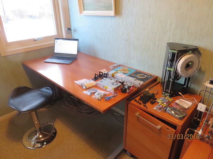
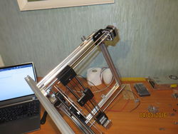
This document is created to try to document a 3D printer build as detailed as possible, to facilitate the development of D3D Workshops. The starting point is an unboxed Folgertech Prusa i3 (see Tobbens_Folgertech_Kit_Unboxing_Log) and the instructions located at Prusa_i3_Modular_Build_Video containing script, Module Assembly Oder 3 module videos module 1, module 2, module 3, as well as time lapses of overall assembly, frame build and extruder slide build. The Folgertech build manual is also used.
Reliability Of Recorded Numbers
Tobben has assembled many RepRaps before, and also read the Module Assembly Order document prior to this logged assembly. Reading took ~10 minutes. Quantifying the relative advantage of previous RepRap experience is very hard, but recorded times should be at least be doubled for novices.
Build steps are performed calmly with no hurry.
No tools are prepared or planned beforehand, so time consumption for getting tools is included.
Nothing on the work-table is touched unless time is recorded. I've tried to avoid solving problems in my head or thinking about specific build steps when the stop watch is not running, so that also the thought work required is captured in the recorded times. Recording thought work with a stop watch is of course impossible to do perfectly.
Stop watch is stopped only while writing this log, taking pictures, eating and going to the toilet.
Log
| Time order | Module | Activity | Time consumed | Time consumed, accumulative | Instruction Resources Used | Comment | Image |
|---|---|---|---|---|---|---|---|
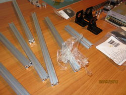
| 1 | Bottom Frame 1 | Removing tape from 2020s | 0:05:46 | 0:05:46 | None | Fiddly | |
| 2 | Bottom Frame 2 | Identifying which beams to use | 0:04:55 | 0:10:41 | Folgertech's Build Manual | Unable to find this info on OSE wiki | |
| 3 | Bottom Frame 3 | Watching Module 1 Video | 0:01:30 | 0:12:11 | module 1 video | Good video | |
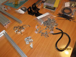
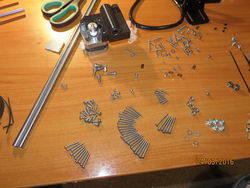
| 4 | Bottom Frame 4 | Very roughly sorting Hardware Bag contents | 0:02:20 | 0:14:31 | |||
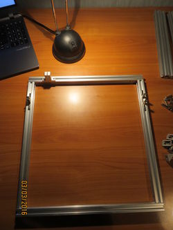
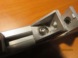
| 5 | Bottom Frame 5 | Assembly of 8 first L-brackets | 0:16:01 | 0:30:32 | module 1 video | Assembly manual: Fill all L-bracket holes with mount screws before inserting into 2020s. Don't use L-shaped hex-key since mounting relies on 2020s lying down flat. | |
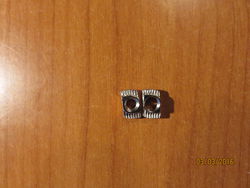
| 6 | Bottom Frame 6 | Confusion regarding the T-nut and screw sizes. | 0:16:54 | 0:47:26 | module 1 video, Folgertech's Build Manual | M4 and M5 T-nuts look very similar. | |
| 7 | Bottom Frame 7 | Assembly of left Y-rod bushings and corner brackets in middle of front beam | 0:09:01 | 0:56:27 | module 1 video | Say in assembly manual: Corner bracket hole sizes are big enough to be able to put T-nut through. Kit comment: M4 screw heads should have been bigger. T-nut and washer fiddling took lots of time. | |
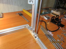
| 8 | Vertical Frame 1 | Assembly and Mounting on Base Frame | 0:33:33 | 1:30:00 | module 1 video | Because of poor corner bracket quality, M4x8 screws are _almost_ too short, and power supply mounting gets very fiddly. | |
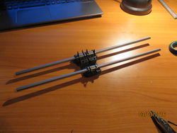
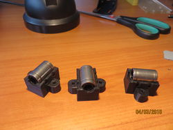
| 9 | X-axis 1 | Faulty Assembly of X-carriage Linear Bearings | 0:09:41 | 1:39:41 | module 2 video | Linear bearings mounted with smooth rod running through. This did not alone prevent the faulty mounting. Kit comment: This error possible because of bad print quality. | |
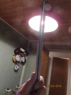
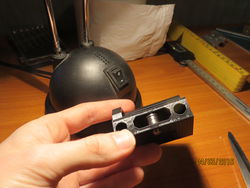
| 10 | X-axis 2 | Faulty Assembly of X-carriage Linear Bearings 2 | 0:10:25 | 1:50:06 | Space for Linear Bearing is too short. Cut out more space by hand with knife. This is weak design since bearing fixation along X-axis is unimportant, so making a tight fit serves no purpose. Process made harder by smooth rods being very far from straight. Video showing bad gliding | ||
| 11 | X-axis 3 | Assembly of X-carriage Linear Bearings | 0:04:59 | 1:55:05 | More manual cutting needed to get Linear Bearings into their tracks. | ||
| 12 | X-axis 4 | Mount Linear Bearings Into X-idlers | 0:03:02 | 1:58:07 | module 2 video | Use paper to wipe off linear bearings, the stuff they're soaked in is not healthy to get on fingers. | |
| 13 | X-axis 5 | Mounting X idler bearings | 0:02:47 | 2:0:54 | module 2 video | Took a guess at which screw to use. | |
| 14 | X-axis 6 | Mounting X Belt pulley and X-motor | 0:08:43 | 2:9:37 | module 2 video | A fair amount of guesswork to find the correct screw length. | |
| 15 | X-axis 7 | Fitting together idlers, carriage and linear rods | 0:01:48 | 2:11:25 | module 2 video | ||
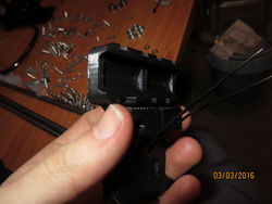
| 16 | X-axis 8 | Thread X-belt | 0:04:29 | 2:15:54 | module 2 video | Slight print error in X-carriage made fastening belt harder. Pushed in place with flat screwdriver. | |
| 17 | Z-axis 1 | Preparing Z-motors | 0:06:50 | 2:22:44 | module 3 video | M3x11 screws... | |
| 18 | Z-axis 2 | Preparing filament guide | 0:02:03 | 2:24:47 | module 3 video | 1 min extra from tool change hex key -> previously unused screw driver -> hex key | |
| 19 | Z-axis 3 | Preparing Z-motors' T-nuts | 0:03:14 | 2:28:01 | module 3 video | ||
| 20 | Y-axis 1 | Manually Enlargening Linear Bearing Holders | 0:13:20 | 2:41:20 | Once again, print error/extremely tight fit by design had to be adjusted with a knife to make linear bearings fit. | ||
| 21 | Y-axis 2 | Threading zip-ties and figuring out how to place printed bearing holders | 0:04:39 | 2:45:59 | Folgertech Build Manual | ||
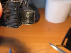
| 22 | Y-axis 3 | Drilling out printed bearing holders' 3mm holes | 0:04:59 | 2:50:58 | Bad prints eat time budgets for lunch. This time, a squeezed out first layer was our enemy, preventing M3 screws from gliding freely. | ||
| 23 | Y-axis 4 | Fastening Y Linear Bearings | 0:09:47 | 3:0:52 | Folgertech Build Manual page 8 | First use of 5 mm spanner. Took extra time because of that. | |
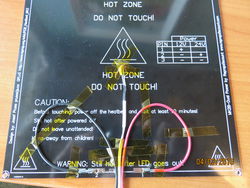
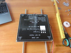
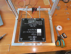
| 24 | Y-axis 5 | Soldering and taping heat bed wires | 0:29:50 | 3:30:42 | Folgertech Build Manual pages 9, 10 and 11 | Taping wires alone took ~10 min. Preparing soldering equipment took ~15 min. | |
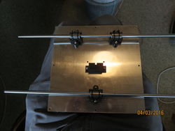
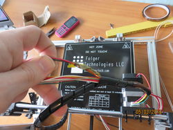
| 25 | Y-axis 6 | Mounting Heat Bed onto Y-Carriage | 0:05:40 | 3:36:30 | Folgertech Build Manual page 11 | Instructions said M3x8 screws. 8mm was impossibly short, used 10 mm ones. | |
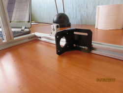
| 26 | Y-axis and Frame 1 | Mount Y-motor mount | 0:02:54 | 3:39:24 | Folgertech Build Manual page 4 | ||
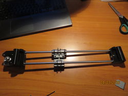
| 27 | Y-axis and Frame 2 | Mounting Y-Carriage | 0:10:40 | 3:50:04 | Mounted left smooth rod only first. Slided in right smooth rod and secured end bushings while Y-carriage fixated the span. | ||
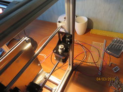
| 28 | Y-axis and Frame 3 | Mounting Y-motor | 0:05:29 | 3:55:33 | Tilt Frame sideways while mounting | ||
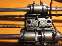
| 29 | Y-axis and Frame 4 | Assembling Y-idler | 0:20:51 | 4:16:24 | Folgertech Build Manual page 20 | I had attached belt holder in the wrong pair of holes in the Y-carriage, so some manual aiming required. Used standard M3 nut instead of nyloc, since nyloc was fiddly. | |
| 30 | Y-axis and Frame 5 | Threading Y-belt | 0:04:37 | 4:21:01 | Mount belt tensioner before tensioning the belt | ||
| 31 | X-axis, Z-axis and Frame 1 | Shortening X-axis and Pushing it in place | 0:07:30 | 4:28:31 | Most time was spent shortening the X-axis. A lot of force needed. | ||
| 32 | X-axis, Z-axis and Frame 2 | Tightening X-belt and right Z-rod bushing screw | 0:03:30 | 4:32:01 | Position belt tensioner here to avoid interfering with microswitch later. | ||
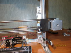
| 33 | X-axis, Z-axis and Frame 3 | Mount left Z-motor | 0:05:44 | 4:37:45 | More easily done when printer is tilted. Insert threaded rod last. Secure it 1 cm below motor shaft. | ||
| 33 | X-axis, Z-axis and Frame 4 | Mount Right Z-motor | 0:06:34 | 4:44:19 | Hold X-axis up close to motor when tightening to assure proper alignment | ||
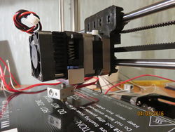
| 34 | X-axis and Extruder 1 | Mount Extruder | 0:09:26 | 4:53:45 | Folgertech Build Manual pages 18 and 19 | Most time was spent screwing M3 screws 30 mm by hand because of poor print qualiy (too small M3 holes). | |
| 35 | Endstop sensors and Frame 1 | Mounting endstops | 0:23:03 | 5:16:48 | Folgertech Build Manual pages 32 and 33 | Microswitch PCB and endstop holder combined differently on all three axes. Very easy to get orientations wrong. | |
| 36 | Electronics 01 | Re-Mounting Power Supply | 0:03:42 | 5:20:30 | Rotate Z-endstop away to more easily access bottom screw. | ||
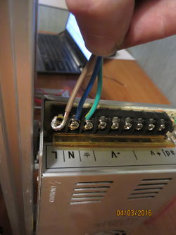
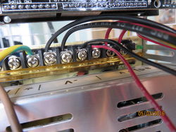
| 37 | Electronics 02 | Attach mains voltage | 0:14:44 | 5:31:32 | Folgertech Build Manual page 35 | Maybe easier to do before re-mounting power supply. All ends are tinned and bent like a hook around screw. | |
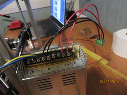
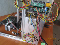
| 38 | Electronics 03 | Attaching RAMPS Power Wires | 0:19:29 | 5:51:01 | Folgertech Build Manual pages 35 and 36 | All ends were tinned, which took a long time. Hooked ends to power supply. | |
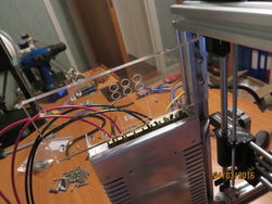
| 39 | Electronics 04 | Attaching Acrylic Mount Plate | 0:03:10 | 5:54:11 | |||
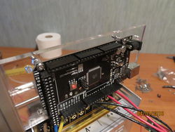
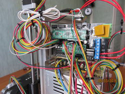
| 40 | Electronics 05 | Mounting RAMPS | 0:08:09 | 6:2:20 | Found no screws of correct length, used my own. | ||
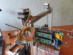
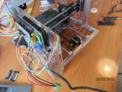
| 41 | Electronics 06 | Wiring Z-motors and bending RAMPS pins into place | 0:06:52 | 6:9:12 | This orientation of cables is reflected in firmware. | ||
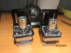
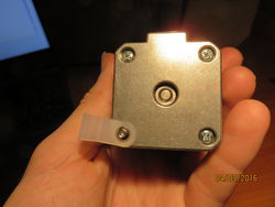
| 42 | Electronics 07 | Wiring Y-motor | 0:05:27 | 6:14:39 | Took 2 min longer because I've mounted Y motor with contacts facing backwards. Getting the connector into the motor was a tight fit. | ||
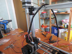
| 43 | Electronics 08 | Wiring X-motor | 0:02:20 | 6:16:59 | Ran out of zip-ties. Had to go get new ones. | ||
| 44 | Electronics 09 | Wrapping Extruder cables in cable guide | 0:05:11 | 6:22:10 | Wrap them all at the same time. This step should have been postponed until after soldering longer fan-cables. | ||
| 45 | Electronics 10 | Connecting 22 gauge wires for Extruder Fan to 12 V | 0:05:42 | 6:27:14 | This step should have been done together with step 38, "Attaching RAMPS Power Wires". Would have saved ca 2 min. | ||
| 46 | Electronics 11 | Soldering fan wires to 22 gauge 12 V wires and wrapping | 0:13:30 | 6:40:44 | This step included some unwinding of cable-guide, preparing soldering iron, stripping wires, finding cable shrink (not included in kit). With a connector or longer fan cables in the first place, this step would have been 2:30. | ||
| 47 | Electronics 12 | Connecting Hot end to RAMPS | 0:08:31 | 6:49:15 | Folgertech Build Manual page 30 | Heater element connectors were tinned. Heater cables a little tricky to strip, took ~1 min more than stripping plastic cables. | |
| 48 | Electronics 13 | Connecting Bed Wires to RAMPS | 0:09:33 | 6:58:48 | Folgertech Build Manual page 29 | Bed heater wires were tinned. These are the most important ones to tin and secure tightly! The instructions from Folgertech told the user to plug the black bed wire into a RAMPS port marked with "+". This felt so wrong, I just couldn't do it. The bed is just acting as a resistor, so it would work either way. | |
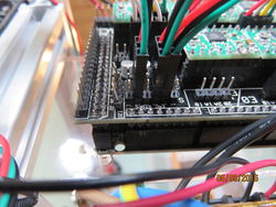
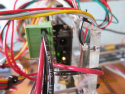
| 49 | Electronics 14 | Connecting Endstops | 0:15:30 | 7:14:18 | Folgertech Build Manual pages 33 and 34 | The Folgertech guide has a bug in it. Near bottom of page 33, it says "There are 6 rows of pins". Every other following statement with pin counts assumes 7 rows of pins. There are really 1 _column_ of four I2C pins and 6 columns of end stop pins. These are ordered like Z_max,Z_min,Y_max,Y_min,X_max,X_min. Therefore, step 23.10 in the Folgertech manual also is a bug, since we have a X_max endstop, not a X_min one. These bugs took 10 min to get straight. | |
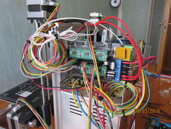
| 50 | Electronics 15 | Final check and Connecting Power | 0:02:46 | 7:17:04 | |||
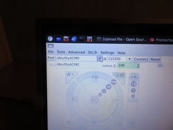
| 51 | Software 1 | Booting D3D Configured Porteus | 0:02:00 | 7:19:04 | D3D_Live_ISO#Computer_Models_Verified_to_Boot | Had to specify /dev/ttyACM0 in Pronterface's drop down menu before pressing "connect". | |
| 52 | Print 1 | Pre-flight Check | 0:25:00 | 7:44:04 | Started a Python script for future automation of this process, published here. | ||
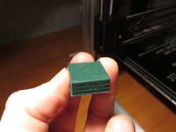
| 53 | Print 2 | First Print | 0:15:21 | 7:59:25 |
Afterthoughts
First of all, the printer works. See video of first print.
However, the assembly is an error-prone process. There are hundreds of common and uncommon mistakes that are easy to do but hard to debug, making the build a risky endeavor for novices.
Pitfall Examples
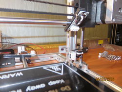
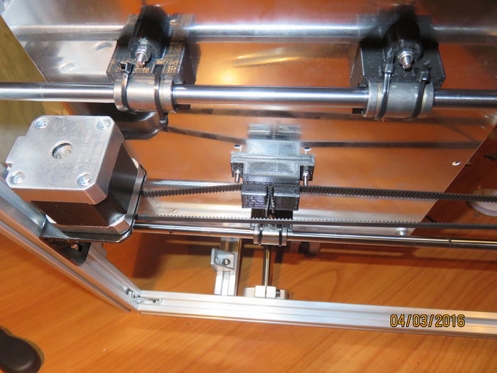
Y-belt mount point that allows belt to come in from the wrong angle:
This would make the pulley work along the leg of an ever-changing triangle instead of a straight line, and big prints' dimensions would be wrong.
