Language Agnostic Instructional Protocol: Difference between revisions
Jump to navigation
Jump to search
No edit summary |
|||
| Line 1: | Line 1: | ||
=Protocol= | |||
#Use a Google Drawing Template - [[IKEA Style Fabrication Diagram Template]] | |||
#Draw out a complete fabrication procedure as best you can - without using words. | |||
#Embed in a wiki page titled Machine/Module Name - IKEA Style Fabrication Diagram. See [[Embedding Google Docs in the Wiki]]. | |||
More detail: | |||
<html><iframe src="https://docs.google.com/presentation/d/1RvbnmUgsYjXXwpwkmBHWn8EuCrJ7TXRR2xGdB2ySXGs/embed?start=false&loop=false&delayms=3000" frameborder="0" width="960" height="569" allowfullscreen="true" mozallowfullscreen="true" webkitallowfullscreen="true"></iframe></html> | |||
[https://docs.google.com/presentation/d/1RvbnmUgsYjXXwpwkmBHWn8EuCrJ7TXRR2xGdB2ySXGs/ edit] | |||
=Intro= | |||
This refers to language-agnostic instructionals. See Example of brick press frame: | |||
<html><img src="https://docs.google.com/drawings/pub?id=14VuV9lJKqF6m9_SpDzIOCj9M_Hk4_46NdyQAh0qd-hc&w=767&h=629"></html> | |||
[https://docs.google.com/drawings/d/14VuV9lJKqF6m9_SpDzIOCj9M_Hk4_46NdyQAh0qd-hc/edit edit] | |||
(see overall documentation from this build in our blog - http://opensourceecology.org/christmas-gift-to-the-world-2012/) | |||
=How to Export Black and White Isometric Drawings from FreeCAD= | |||
[https://www.youtube.com/watch?v=V_i_jAhE_JU Video guide how to export FreeCAD's view to black and white with macro and gimp] | |||
<html><iframe width="560" height="315" src="https://www.youtube.com/embed/V_i_jAhE_JU" frameborder="0" allowfullscreen></iframe></html> | |||
<html><iframe src="https://docs.google.com/presentation/d/1zSDe5WbCFVKougqYPusOH_rOenriTHt5NzX45bTl6r4/embed?start=false&loop=false&delayms=3000" frameborder="0" width="960" height="569" allowfullscreen="true" mozallowfullscreen="true" webkitallowfullscreen="true"></iframe></html> | <html><iframe src="https://docs.google.com/presentation/d/1zSDe5WbCFVKougqYPusOH_rOenriTHt5NzX45bTl6r4/embed?start=false&loop=false&delayms=3000" frameborder="0" width="960" height="569" allowfullscreen="true" mozallowfullscreen="true" webkitallowfullscreen="true"></iframe></html> | ||
| Line 36: | Line 72: | ||
<html><iframe width="560" height="315" src="https://www.youtube.com/embed/LocSkUoD1ic" frameborder="0" allowfullscreen></iframe></html> | <html><iframe width="560" height="315" src="https://www.youtube.com/embed/LocSkUoD1ic" frameborder="0" allowfullscreen></iframe></html> | ||
=Examples of OSE Machines= | |||
*CEB full instructionals from 2012 - [[CEB_Press_Language_Agnostic_Instructionals]] | |||
*[[D3D Language Agnostic Instructionals]] | |||
Revision as of 19:43, 16 May 2017
Protocol
- Use a Google Drawing Template - IKEA Style Fabrication Diagram Template
- Draw out a complete fabrication procedure as best you can - without using words.
- Embed in a wiki page titled Machine/Module Name - IKEA Style Fabrication Diagram. See Embedding Google Docs in the Wiki.
More detail:
Intro
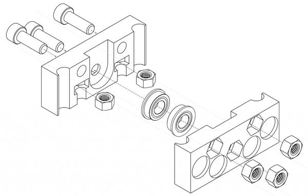
This refers to language-agnostic instructionals. See Example of brick press frame:
(see overall documentation from this build in our blog - http://opensourceecology.org/christmas-gift-to-the-world-2012/)
How to Export Black and White Isometric Drawings from FreeCAD
Video guide how to export FreeCAD's view to black and white with macro and gimp
Extracting Black and White Isometric Drawings from FreeCAD
Before you work with a file, make sure that the file is approved according to OSE CAD Standards.
GIMP + FreeCAD Macro
- Here is a method from Laszlo using GIMP and a FreeCAD macro script.
Inkscape + FreeCAD Drawing Workbench
Roberto Isometric view workflow. This method works fine for parts with regular surfaces (most). I couldn't make it work for wires.
- Open a FreeCAD file with the part you want to extract the isometric view from.(If the wanted part is separated in several smaller parts, go to Part Workbench, select all of these parts and use the tool "Make compound" in the top dropdown menu).
- Go to Drawing Workbench (It seems that Drawing Workbench do the same work faster than Drawing_dimensioning Workbench).
- Use tool named: "Insert new drawing", I chose A3 Landscape (Plain).
- Select the wanted part, by double clicking over it.
- Change to the new drawing page.
- Use tool named: "Insert an orthographic projection of a part in the active drawing" and wait.
- Select another view in Secondary views (just click in other little square). Wait.
- Set "Axis aligned up" option to "X +ve" (try different options until get desired perspective). Wait.
- Click OK.
- Delete the unneeded drawings.
- Use the tool: "Recomputes the current active document" to refresh the drawing.
- You can repeat steps 4-11 for adding another part's isometric view to the same sheet.
- You can change position and scale for each drawing in the combo view data tab (after selecting the wanted drawing).
- You can select the Drawing page and use the tool: "Export a page to a SVG file". I'm planning to use these SVG files to do the LAIs.
Sample:
https://docs.google.com/drawings/d/1LOOY4nSUzN7kKiybVwX7-Y33eCFuB39NJQO4BMZE5aY/edit
Examples of OSE Machines
- CEB full instructionals from 2012 - CEB_Press_Language_Agnostic_Instructionals
- D3D Language Agnostic Instructionals
