OSE Piping Workbench: Difference between revisions
(add documentation about tees in ose piping workbench) |
(add documentation about corners in ose piping workbench) |
||
| Line 1: | Line 1: | ||
{{Hint|See Workbench Source Code at '''[[PVC_Pipe_and_Fittings_Library#OSE_Piping_Workbench]]'''}} | {{Hint|See Workbench Source Code at '''[[PVC_Pipe_and_Fittings_Library#OSE_Piping_Workbench]]'''}} | ||
= Introduction = | =Introduction= | ||
The OSE pipe workbench is a FreeCAD workbench with pipes and fittings. It creates pipes and fitting using FreeCAD Parts workbench and [https://github.com/oddtopus/flamingo Flamingo]. | The OSE pipe workbench is a FreeCAD workbench with pipes and fittings. It creates pipes and fitting using FreeCAD Parts workbench and [https://github.com/oddtopus/flamingo Flamingo]. | ||
| Line 32: | Line 32: | ||
Useful links: [https://www.aetnaplastics.com/site_media/media/attachments/aetna_product_aetnaproduct/204/PVC%20Sch%2040%20Fittings%20Dimensions.pdf] | Useful links: [https://www.aetnaplastics.com/site_media/media/attachments/aetna_product_aetnaproduct/204/PVC%20Sch%2040%20Fittings%20Dimensions.pdf] | ||
= Couplings = | =Couplings= | ||
A (general) coupling is described by dimensions: POD, POD1, PID, PID1, L, M, M1, N. The dimensions POD1 and PID1 are not from a official specifications. | A (general) coupling is described by dimensions: POD, POD1, PID, PID1, L, M, M1, N. The dimensions POD1 and PID1 are not from a official specifications. | ||
| Line 45: | Line 45: | ||
= Bushings = | =Bushings= | ||
A bushing is described by dimensions N, L and pipe dimensions. As pipe dimensions we use POD, PID1, and POD1. | A bushing is described by dimensions N, L and pipe dimensions. As pipe dimensions we use POD, PID1, and POD1. | ||
| Line 66: | Line 66: | ||
To add a new tee to the part list, adjust '''tee.csv''' in ''tables'' directory within workbench directory. | To add a new tee to the part list, adjust '''tee.csv''' in ''tables'' directory within workbench directory. | ||
=Corners= | |||
= Programming = | An corner is described by dimensions G, H, M and pipe dimensions. As pipe dimensions we use POD and PID. | ||
To create a corner, click [[File:CreateCorner.svg]] in OSE piping workbench. | |||
[[File:create-corner-screenshot.png|512px]] | |||
[[File:create-corner-cad-screenshot.png|thumb]] | |||
To add a new corner to the part list, adjust '''corner.csv''' in ''tables'' directory within workbench directory. | |||
=Programming= | |||
* [https://www.freecadweb.org/wiki/Scripted_objects FreeCAD scripted object] | * [https://www.freecadweb.org/wiki/Scripted_objects FreeCAD scripted object] | ||
* It should be possible to represent the object with "classic" FreeCAD forms like cylinders, spheres, sweeping objects ... | * It should be possible to represent the object with "classic" FreeCAD forms like cylinders, spheres, sweeping objects ... | ||
| Line 73: | Line 83: | ||
* The main purpose is to create tools for moving, rotations, and fittings. | * The main purpose is to create tools for moving, rotations, and fittings. | ||
= Documentation = | =Documentation= | ||
* [https://www.freecadweb.org/wiki/Scripted_objects FreeCAD scripted objects] | * [https://www.freecadweb.org/wiki/Scripted_objects FreeCAD scripted objects] | ||
* [https://forum.freecadweb.org/viewtopic.php?f=8&t=27641&sid=0f829d3bd056ec5add5407879796451a Forum entry on freecadweb.org] | * [https://forum.freecadweb.org/viewtopic.php?f=8&t=27641&sid=0f829d3bd056ec5add5407879796451a Forum entry on freecadweb.org] | ||
Revision as of 17:35, 25 March 2018
![]() Hint: See Workbench Source Code at PVC_Pipe_and_Fittings_Library#OSE_Piping_Workbench
Hint: See Workbench Source Code at PVC_Pipe_and_Fittings_Library#OSE_Piping_Workbench
Introduction
The OSE pipe workbench is a FreeCAD workbench with pipes and fittings. It creates pipes and fitting using FreeCAD Parts workbench and Flamingo.
Pipes
The dimensions of the PVC pipes can be found here PVC_Pipe. Wikipedia on Nominal Pipe Size (NPS) [1],
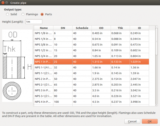
A pipe is described by its outer diameter OD, its wall thickness Thk and its height[1] H.
To create a pipe, click  in OSE piping workbench. Select pipe dimensions and click "OK".
To add new dimensions adjust CSV pipe.csv in tables directory within workbench directory to add new pipe dimensions to the list.
Elbows
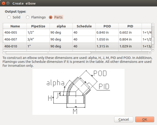
An elbow is described by an angle alpha, outer pipe diameter POD, inner pipe diameter PID, H, J, M.
To create an elbow, click  in OSE piping workbench.
To add new elbows, adjust elbow.csv in tables directory within workbench directory.
Useful links: [2]
Couplings
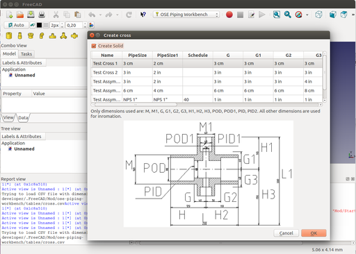
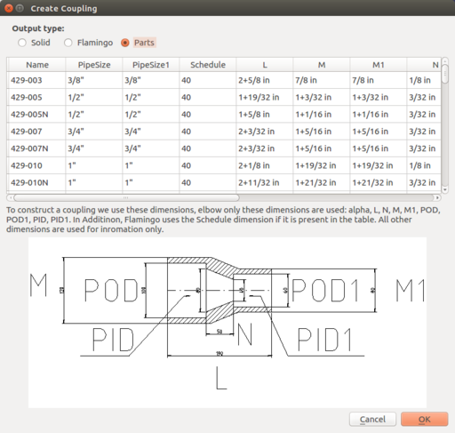
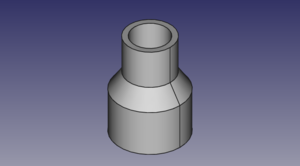
A (general) coupling is described by dimensions: POD, POD1, PID, PID1, L, M, M1, N. The dimensions POD1 and PID1 are not from a official specifications. They are derived from pipe size and schedule. In a reducer coupling, the pipe dimensions on one side POD and PID differ from on the other side POD1 and PID1.
To create a coupling, click  in OSE piping workbench.
To add new couplings, adjust coupling.csv in tables directory within workbench directory.
Bushings
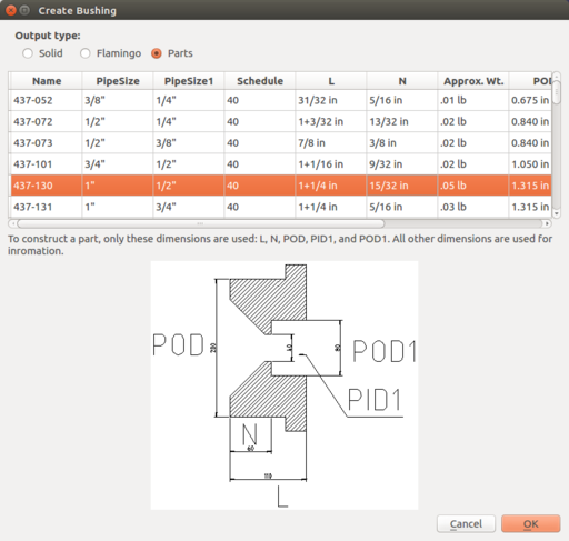
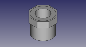
A bushing is described by dimensions N, L and pipe dimensions. As pipe dimensions we use POD, PID1, and POD1.
To create a bushing, click  in OSE piping workbench.
To add a new coupling to the part list, adjust bushing.csv in tables directory within workbench directory.
Tees
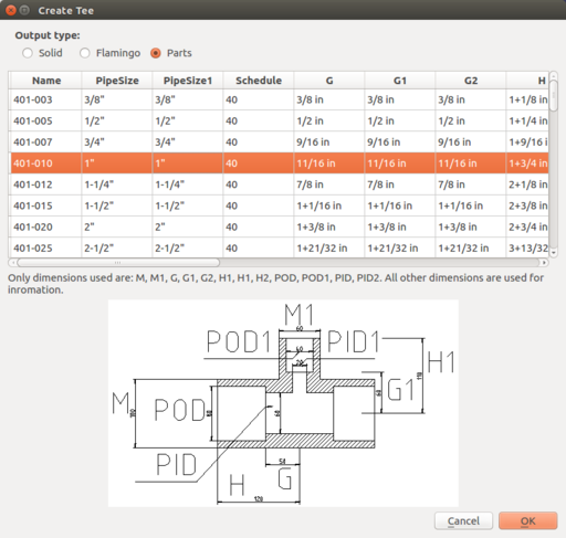
A tee is described by parameters G, G1, H, H1, M, M1, and pipe dimensions. As pipe dimensions we use POD, POD1, PID, and PID1.
To create a tee click  in OSE piping workbench.
To add a new tee to the part list, adjust tee.csv in tables directory within workbench directory.
Corners
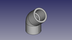
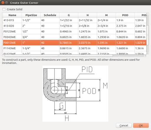
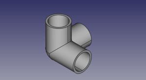
An corner is described by dimensions G, H, M and pipe dimensions. As pipe dimensions we use POD and PID.
To create a corner, click  in OSE piping workbench.
To add a new corner to the part list, adjust corner.csv in tables directory within workbench directory.
Programming
- FreeCAD scripted object
- It should be possible to represent the object with "classic" FreeCAD forms like cylinders, spheres, sweeping objects ...
- It should be possible to use solids.
- The main purpose is to create tools for moving, rotations, and fittings.
Documentation
- ↑ We use height instead of length in order to make a pipe similar to a FreeCAD cylinder. These particular choice of pipe dimensions make it more compatible with pipes from flamingo workbench.
