Angle Frame Connector: Difference between revisions
Jump to navigation
Jump to search
No edit summary |
(→Build) |
||
| Line 1: | Line 1: | ||
=Build= | =Build= | ||
<html><iframe src="https://www.facebook.com/plugins/post.php?href=https%3A%2F%2Fwww.facebook.com%2Fmarcin.jakubowski.378%2Fposts%2F10217604990773755&width=500" width="500" height="378" style="border:none;overflow:hidden" scrolling="no" frameborder="0" allowTransparency="true" allow="encrypted-media"></iframe></html> | <html><iframe src="https://www.facebook.com/plugins/post.php?href=https%3A%2F%2Fwww.facebook.com%2Fmarcin.jakubowski.378%2Fposts%2F10217604990773755&width=500" width="500" height="378" style="border:none;overflow:hidden" scrolling="no" frameborder="0" allowTransparency="true" allow="encrypted-media"></iframe></html> | ||
[[File:angleconnectorframe.jpg|400px]] | |||
=CAD= | =CAD= | ||
Revision as of 22:29, 29 October 2019
Build

CAD


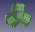
Angle Connector. - FreeCAD with McMaster 6 mm nut -File:Angleconnector.fcstd. Finished STL - File:Anglecorner.stl
Concept
Production
- 50% infill for real print.
- Test print at 20%: 10 cm cut off the bottom, standing on corner - . This would not stand on moving-bed printers. Babystepping correction -0.75. It does not stand on a stationary bed printer eiether. I turned it around to print standing on 6 points.

- Came off bed so printed it on 6 corners:
- Initial fit: metal shown with 6 mm hex nut and set screw in the hole.
- STL - sunk 5 mm into bed. Test print at 20%, takes 8.5 hrs. Production print: 50% infill, 10:10 hours, 133 g. Brim 10 lines. Prints starting on 6 corners, for a solid base.
