Solar Collector Calculations: Difference between revisions
No edit summary |
|||
| Line 73: | Line 73: | ||
The highest achievable temperature in our collector will be determined by how quickly it loses energy (function of temperature) compared to how quickly it receives energy (constant determined by collector array) | The highest achievable temperature in our collector will be determined by how quickly it loses energy (function of temperature) compared to how quickly it receives energy (constant determined by collector array) | ||
==Reflection Through a Glass Surface== | |||
The graph of transmittance vs. angle at http://irc.nrc-cnrc.gc.ca/pubs/cbd/cbd039_e.html shows about 10% reflectance or slightly higher for the angle which concern us. | |||
==Conduction through walls of absorber== | ==Conduction through walls of absorber== | ||
Revision as of 15:33, 1 July 2008
Losses due to edge effects and lack of daily tracking
If we use a passive tracking arrangement for the collector, with only seasonal adjustment, then we have two losses:
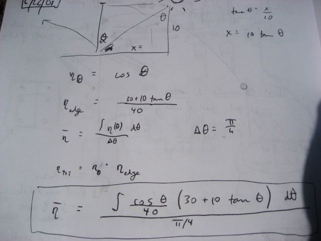
- Loss due to the sun not being perpendicular to the array - if theta is the angle measured from the position of the sun at high noon - then the efficiency stemming from this varies as cosine(theta)
- Loss due to edge effects - when the sun is not directly overhead, part of the collector tube is not illuminated (assuming length of collector tube is the same as the length of the reflectors)
The overall average efficiency (eta bar) considering these two losses - for the 6 hours of the day around high noon - is:
This value - I estimate to be around 75% - for the average efficiency of the collector without daily tracking.
Someone please run this on the computer or analytically and fill in the exact value.
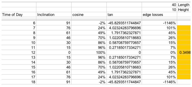
Losses due to edge effects only
For a 40x10 foot solar collector array, with length running East to West, this is a table of losses corresponding to the edge efficiencies (Greek eta_edge) represented by the
term in the above equations:
Vapor Generation Rate
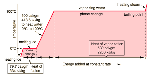
Based on water, we have:
generating steam
the energy needed to heat a mass of water is given by:
E = M * Specific heat * change in temp
The Energy needed to vaporize a mass of water is given by:
E = M * heat of vaporization
The energy needed to raise the temperature of the water and then vaporize it is the sum of the two. Because we are dealing with power instead of energy, we can replace mass by the mass flow (g/S).
Power = Massflow * (Specific heat * change in temp + Heat of vap)
or
Massflow = P / (Specific heat * change in temp + Heat of vap)
for our specific case:
Power = 20,000 J/s (20 Kw)
Change in temp = 300 C (from room temperature to 330 C)
specific heat= 4J/g
heat of vaporization=2,226 J/g
Mass Flow= 5.64 g/s or 44 lb/Hour
if change in temp is 150C, corresponding to producing steam at 180C and roughly 10 atm (140 psi) then the mass flow is 7.07 g/s or 56 lb/Hour
Superheating Steam
Superheating the steam requires an additional input of energy
Specific heat of steam: 1/2 Cal/g/C = 2 kJ/kg/C
Thermal losses through absorber (conduction and radiation)
The highest achievable temperature in our collector will be determined by how quickly it loses energy (function of temperature) compared to how quickly it receives energy (constant determined by collector array)
Reflection Through a Glass Surface
The graph of transmittance vs. angle at http://irc.nrc-cnrc.gc.ca/pubs/cbd/cbd039_e.html shows about 10% reflectance or slightly higher for the angle which concern us.
Conduction through walls of absorber
assuming a 40 ft x .5ft rectangular absorber box with an open bottom (11.3 square meters, we'll just ignore the complexity of corners).
using 1 inch of rigid fiberglass of R-value 4 (in SI units) and assuming a temperature difference of 200 degree Celsius (outside surface is cool to the touch).
Power lost due to conduction = 1/R * A * (delta T) = 278 watts.
losses through the bottom due to radiation and conduction
Assume perfect thermal pooling, so no loss due to convection of gases.
Assume perfect absorption, no reflection of energy (black body)
P = A * o * e * (T1^4 - T2^4)
Area of absorber = 40 ft x .5 ft = 1.86 meters squared
o (supposed to be a sigma, representing the Stefan–Boltzmann constant) = 5.67 x 10^-8 in SI units
e = emmisivity
t1 = 230 degree celsius = 503 K
t2 = 30 C = 293 K
for e = 1 (regular black paint)
P = 5973 Watts
for e = .1 (solar selective surface)
P = 597.3 Watts
How do we calculate conduction through the air out of the absorber?
Theoretical maximum achievable temperature
find the Temperature that balances losses (as given by the above equations) and the power received from mirror array.


