Solar Collector Calculations
Losses due to edge effects and lack of daily tracking
If we use a passive tracking arrangement for the collector, with only seasonal adjustment, then we have two losses:
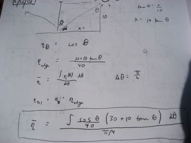
- Loss due to the sun not being perpendicular to the array - if theta is the angle measured from the position of the sun at high noon - then the efficiency stemming from this varies as cosine(theta)
- Loss due to edge effects - when the sun is not directly overhead, part of the collector tube is not illuminated (assuming length of collector tube is the same as the length of the reflectors)
The overall average efficiency (eta bar) considering these two losses - for the 6 hours of the day around high noon - is:
This value - I estimate to be around 75% - for the average efficiency of the collector without daily tracking.
Someone please run this on the computer or analytically and fill in the exact value.
Losses Due to Air Mass
The lower that the sun is over the horizon, the larger the thickness of the atmosphere that the sun has to travel through. This reduces the solar income. Air mass calculator:
http://www.udel.edu/igert/pvcdrom/SUNLIGHT/AIRMASS.HTM
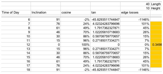
Losses due to edge effects only
For a 40x10 foot solar collector array, with length running East to West, this is a table of losses corresponding to the edge efficiencies (Greek eta_edge) represented by the
term in the above equations:
Vapor Generation Rate
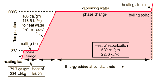
Based on water, we have:
generating steam
the energy needed to heat a mass of water is given by:
E = M * Specific heat * change in temp
The Energy needed to vaporize a mass of water is given by:
E = M * heat of vaporization
The energy needed to raise the temperature of the water and then vaporize it is the sum of the two. Because we are dealing with power instead of energy, we can replace mass by the mass flow (g/S).
Power = Massflow * (Specific heat * change in temp + Heat of vap)
or
Massflow = P / (Specific heat * change in temp + Heat of vap)
for our specific case:
Power = 20,000 J/s (20 Kw)
Change in temp = 300 C (from room temperature to 330 C (603K) )
specific heat= 4J/g
heat of vaporization=2,226 J/g
Mass Flow= 5.64 g/s or 44 lb/Hour
if change in temp is 150C, corresponding to producing steam at 180C and roughly 10 atm (140 psi) then the mass flow is 7.07 g/s or 56 lb/Hour
Superheating Steam
Superheating the steam requires an additional input of energy
Specific heat of steam: 1/2 Cal/g/C = 2 kJ/kg/C
Thermal losses through absorber (conduction and radiation)
The highest achievable temperature in our collector will be determined by how quickly it loses energy (function of temperature) compared to how quickly it receives energy (constant determined by collector array)
Reflection From a Glass Surface
The graph of transmittance vs. angle at http://irc.nrc-cnrc.gc.ca/pubs/cbd/cbd039_e.html shows about 10% reflectance or slightly higher for the angle which concern us.
Transmission of Sunlight Through a Glass Surface
Composition of Sunlight - [1]
Transmission through glass - [2]
Wavelength radiated from flat black absorber - modify graph here for 500K
Conduction through walls of absorber
assuming a 40 ft x .5ft rectangular absorber box with an open bottom (11.3 square meters, we'll just ignore the complexity of corners).
using 1 inch of rigid fiberglass of R-value [3] 4 (in SI units) and assuming a temperature difference of 200 degree Celsius (outside surface is cool to the touch).
Power lost due to conduction = 1/R * A * (delta T)[4] = 278 watts.
losses through the bottom due to radiation and conduction
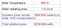
Blackbody radiation for a surface at 500K is significant. There is a downloadable spreadsheet in Excel - and it verifies our numbers. The spreadsheet result is pasted here:
Assume perfect thermal pooling, so no loss due to convection of gases.
Assume perfect absorption, no reflection of energy (black body)
P = A * o * e * (T1^4 - T2^4)
Area of absorber = 40 ft x .5 ft = 1.86 meters squared
o (supposed to be a sigma, representing the Stefan–Boltzmann constant) = 5.67 x 10^-8 in SI units [5]
e = emmisivity
t1 = 230 degree celsius = 503 K
t2 = 30 C = 293 K
for e = 1 (regular black paint) P~1.86*5.67^(-8)*6^(10)
P ~ 6000W
for e = .1 (solar selective surface)
P ~ 600W
How do we calculate conduction through the air out of the absorber?
Start with [6] for conductivity power loss and constants:
Thermal conductivity power loss - H
H = kA(Delta T)/L ~ 20 Watts
k~0.03
A~2 square meters
delta T ~ 200 C
L ~ .5 m - assume this is the gradient length between 200C and 20C.
Theoretical maximum achievable temperature
The stagnation temperature is the temperature reached when no power is being absorbed by a heat transfer fluid. Thus, the system is just getting hot, and not doing any work.
assuming 20000 Watts of power effectively being delivered to the absorber, the stagnation temperature is solved for by finding the temperature where thermal power dissipation is equal to power input:
Case 1: no glass and regular black paint on absorber
20000 = (1/20)*11.3*(t - 293) + 1.86*(5.67*10^-8)*1*(t^4 - 293^4) + .03*2*(t - 293)/.5
then t = 664K or 391C
Case 2: Solar selective surface with emissivity of .9 for solar radiation and .1 for blackbody dissipation:
18000 = (1/20)*11.3*(t - 293) + 1.86*(5.67*10^-8)*.1*(t^4 - 293^4) + .03*2*(t - 293)/.5
Then t = 1134K or 861K
Operating temperature
By drawing power from the absorber (non-stagnation) we reduce the operating temperature.
For case 1, we can draw 18kW at 400K or 127C. we can draw 15kW at 481K or 208C.
For case 2, we can draw 18kW at room temperature. We can draw 15kW at 717K or 444C
Absorber efficiency and operating temperature
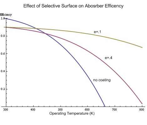
This plot was made on Mathematica using the equation
Efficency = Energy used/total energy in = (Input energy - energy losses)/Input energy
 where Input energy was 20000 times the optical efficency (1 for no coating, .9 for a coating)
 and e was 1, .4 and .1 for the different curves.
 Energy losses included radiative losses as well as conduction through the back insulation and
 conduction out the aperature.  Changing the R values for convective and conductive losses however
 does not noticeably change the curves.
(0 Celsius = 273 Kelvin)
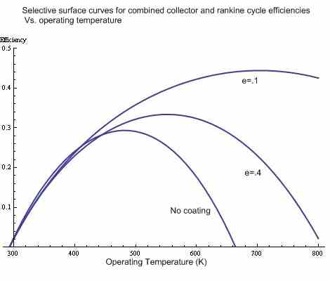
Choosing the operating point
Here, the above curves were multiplied by the Carnot efficiency (assuming an exhaust temperature of 293K = 30C) to determine the total efficiency of the absorber and Rankine cycle. The operating temperature that gives the highest efficiency is the theoretical ideal operating point for the system.
note: the rankine efficency begins to deviate from the Carnot efficiency at higher temperatures (i don't know by how much), thus this graph is just slightly optimistic.
By operating temperature it is meant the temperature of vaporization, which is roughly the average temperature of heat addition. this is the temperature that corresponds to the Carnot ideal, as opposed to the maximum temperature of superheated steam.
note: The critical temperature for water is 647K.
Summary: Available Power
Detailed heat transfer calculations are beyond the scope of the study prior to August 15, 2008. However, these are the working baselines:
- Heat gain from solar reflectors is nominally 20 kW
- Blackbody radiation is significant at high temperature.
- Conduction from the back side is insignificant when we use sufficient insulation
- Blackbody radiation is determined by temperature of collector tube
- Temperature of collector tube is determined by heat usage by the heat engine
- Flat black paint allows full solar absorption
- Glass with selective coating addresses the blackbody radiation problem [7]
