Quick Connect Wheels: Difference between revisions
No edit summary |
|||
| Line 40: | Line 40: | ||
<html><iframe width="300" height="233" src="https://www.youtube.com/embed//hICQOCHkDsk" frameborder="0" allowfullscreen></iframe></html> | <html><iframe width="300" height="233" src="https://www.youtube.com/embed//hICQOCHkDsk" frameborder="0" allowfullscreen></iframe></html> | ||
. | . | ||
| Line 66: | Line 65: | ||
Download the relation to frame, STEP and X_T files - [[File:wheelmodel2.zip]] | Download the relation to frame, STEP and X_T files - [[File:wheelmodel2.zip]] | ||
==Reducing loads on the shafts and bearings== | |||
In order to reduce the bending load of the shaft the following design could be implemented: | |||
[[Image:Wheelmodel_3.png]] | |||
The idea is moving the main bearing as close to the wheel center as possible. This will reduce the bending moment on the shaft close to zero and reduce the loads on the bearings. The roller element bearing close to the motor could actually be replaced now by a much smaller one. | |||
In this design the 4"x4" transverse tube takes over the whole bending moment for transferring the forces from the wheel to the frame. There are different possibilities for anchoring this tube to the frame. One should only keep in mind that the loads will push the external frame tube upwards and pull the internal one downwards. | |||
You can download the CAD model of this first rough design in the following file | |||
Download [[File:Wheelmodel_3.FCStd]] | |||
=Solution Pathways for Addressing Failing Motor Couplers= | =Solution Pathways for Addressing Failing Motor Couplers= | ||
Revision as of 09:51, 6 December 2011
Introduction
LifeTrac wheel couplers suffered catastrophic failure when used with tracks.
.
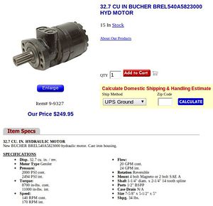
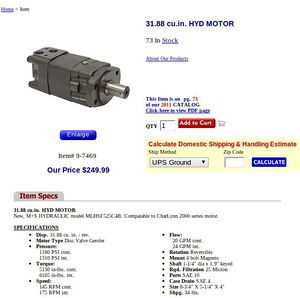
The key on the motor shaft sheared. We put on thicker couplers, and LifeTrac currently works - but we will not take it through destructive testing prior to testing splined motors. NOTE: Discussion at 31.88 Cubic Inch Motors shows hints that pressure setting was too high, and could have been the reason for failure.
.
It is suspected that the 4-wheel drive, when coupled by wheel tracks, makes the motors fight each other.
Removing Tracks, Adding Quick Connect Wheels
To remedy the failing coupler, we will remove the tracks as the first step, and run the motors in series to simplify control valve requirements. That means that a 3000 PSI pump can deliver a max of 1500 PSI to each motor. This puts a low limit on the pressure, while delivering 6525 in lb for each motor - which makes this still higher torque than the 5000 cu in former 31.88 cu in motors used on LifeTrac I-III.
The rough concept of a quick connect wheel is this:
Implementation
To design the quick connect wheel, complete LifeTrac Frame geometry must be considered.
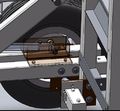
See pictures of wheeel:
and the real object:
.
Concept Quick Release Wheel
Design Rationale:
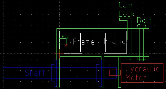
- Triple mechanism of holding using peg, a cam lock, and a bolt:
Download File:Wheelmount.dxf
See it:
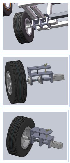
Model:
Download pngs of above and STEP file - File:Wheelmodel.zip
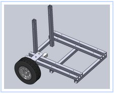
Relation to frame:
Download the relation to frame, STEP and X_T files - File:Wheelmodel2.zip
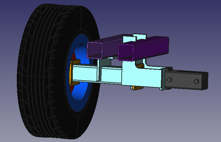
Reducing loads on the shafts and bearings
In order to reduce the bending load of the shaft the following design could be implemented:
The idea is moving the main bearing as close to the wheel center as possible. This will reduce the bending moment on the shaft close to zero and reduce the loads on the bearings. The roller element bearing close to the motor could actually be replaced now by a much smaller one.
In this design the 4"x4" transverse tube takes over the whole bending moment for transferring the forces from the wheel to the frame. There are different possibilities for anchoring this tube to the frame. One should only keep in mind that the loads will push the external frame tube upwards and pull the internal one downwards.
You can download the CAD model of this first rough design in the following file
Download File:Wheelmodel 3.FCStd
Solution Pathways for Addressing Failing Motor Couplers
Solution Pathway 1
Concept:
- Use a motor with more torque
- Direct coupling to wheel eliminates bearings, shafts, and collars
- Retain tracks
- Use one motor per side to eliminate motors 'fighting each other'
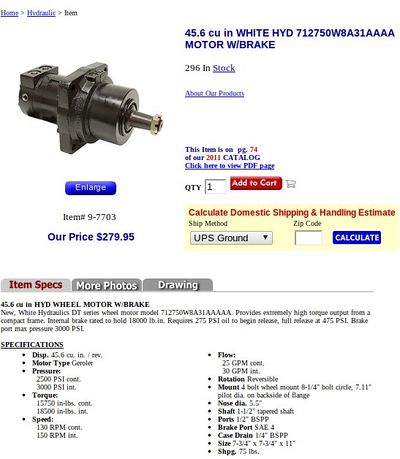
Possible solution: 15,000 Inch Pound Motor
Solution Pathway 2
- Use 2 motors per side, and same drive train as in LifeTrac Wheel Assembly Video, but with splined shaft motors
- Do motors 'fight each other' in this case?
- The new splined motors are these from Surpluscenter:
Pathway 3
- Reduce pressure on hydraulic motors?
- 1160 PSI only is max on 31.88 Cubic Inch Motors. Is this sufficient to drive the tractor?
Peer Review
This page should be peer reviewed by hydraulics specialists, such as at hydraulics forums.

