PowerCube Hydraulic reservoir: Difference between revisions
Jump to navigation
Jump to search
Tom Griffing (talk | contribs) |
Tom Griffing (talk | contribs) |
||
| Line 11: | Line 11: | ||
#. Cut two 1 7/16" holes and one 2" hole in the tube as in the diagram below. | #. Cut two 1 7/16" holes and one 2" hole in the tube as in the diagram below. | ||
#. Tack and weld the 3/4" flanges to the smaller holes with smooth, consistent welds to insure no leaks. | #. Tack and weld the 3/4" flanges to the smaller holes with smooth, consistent welds to insure no leaks. | ||
#. Tack and weld the 2" x 2" diameter pipe to the reservoir, insuring that it is centered over the reservoir hole. Once welded, perform a "dry fit" by inserting the strainer into the extension tube to verify no binding when centered. | #. Tack and weld the 2" x 2" diameter pipe to the reservoir, insuring that it is centered over the reservoir hole. Once welded, perform a "dry fit" by inserting the strainer into the extension tube to verify no binding when centered. | ||
#. Tack and weld the larger flange to the end of the extension pipe. Again, perform the "dry fit" to insure no binding on the strainer. | #. Tack and weld the larger flange to the end of the extension pipe. Again, perform the "dry fit" to insure no binding on the strainer. | ||
#. Use a wire brush to thoroughly clean the inside of the tube. | #. Use a wire brush to thoroughly clean the inside of the tube. | ||
#. Tack and weld the two end plates to the tube, again with smooth consistent weld to insure no leaks. | #. Tack and weld the two end plates to the tube, again with smooth consistent weld to insure no leaks. | ||
Revision as of 04:13, 14 December 2011
Hydraulic reservoir
This is the assembly for welding the hydraulic reservoir. Keep the strainer away from welding sparks, as its fine metal mesh melts easily.
- [2] ¼” x 6” x 12”
- 6” x 12” x 27 ½” Tube
- 2” x 2” x 1/8” Tube
- [2] 3/4" Forged Weld-in Flange
- 1 1/2" Forged Weld-in Flange
- Suction strainer
- . Cut two 1 7/16" holes and one 2" hole in the tube as in the diagram below.
- . Tack and weld the 3/4" flanges to the smaller holes with smooth, consistent welds to insure no leaks.
- . Tack and weld the 2" x 2" diameter pipe to the reservoir, insuring that it is centered over the reservoir hole. Once welded, perform a "dry fit" by inserting the strainer into the extension tube to verify no binding when centered.
- . Tack and weld the larger flange to the end of the extension pipe. Again, perform the "dry fit" to insure no binding on the strainer.
- . Use a wire brush to thoroughly clean the inside of the tube.
- . Tack and weld the two end plates to the tube, again with smooth consistent weld to insure no leaks.
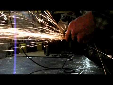
Welding extension and flange


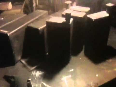
- Video of reservoirs after welding:
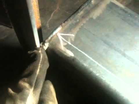
- After tack welding - measure location of engine mount 8 inches from inner edge of frame (not hydraulic tank) and 3 inches down from top of hydraulic tank: