CEB Press/Manufacturing Instructions/ElectrohydraulicIntegration: Difference between revisions
James Slade (talk | contribs) |
|||
| Line 7: | Line 7: | ||
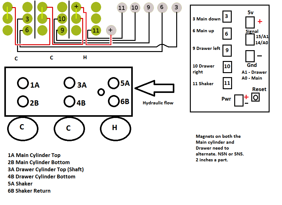
=Wiring Diagram= | =Wiring Diagram= | ||
[[Image: | [[Image:ElectrohydraulicIntegration_part2.png]] | ||
=Assembly of the Electrohydraulic Integration= | =Assembly of the Electrohydraulic Integration= | ||
Revision as of 06:04, 14 April 2012
Video
Wiring Diagram
Assembly of the Electrohydraulic Integration
Note that this process should occur only if the solenoid valve set and controller box are already mounted on the CEB press. The process is shown separately from the CEB press for clarity.
Tools
- Screwdriver with Number 2 Philips Bit
- Straight Pattern Tin Snips
- Wire Strippers compatible with 18 gauge
- Crimper
- 10mm Hex Key
- Measuring Tape
Materials
- Controller Box
Ensure that the connections between the top 5 terminals of the terminal platform and the left 5 (MOSFET) terminals of the solenoid driver are such that left to right (terminal platform) corresponds with bottom to top (solenoid driver), respectively. In this case, from left to right the top terminals of the terminal platform are indirectly connected to Arduino pins 11, 10, 9, 6, and 3, respectively.
- Solenoid Valve Set
Ensure that the solenoid valves are mounted to the subplate such that, when the work ports open away from you, from left to right the solenoid valve types are C, C, and H, respectively.
- 18 Gauge Red Wire
- [4] Ring Insulated 14-16 Gauge Connectors
Steps
- Using the tin snips, cut 2 pieces of 30cm red wire.
- Using the wire strippers, strip 1cm at all ends of the 2 pieces of red wire.
- Using the crimpers, crimp the ring connectors at all ends of the 2 pieces of red wire.
- Orient the solenoid valve set such that its work ports open away from you.
- Using the hex key, unscrew the 3 hex caps closer to you.
- Using the screwdriver with the number 2 philips bit, unscrew and remove the lids of the solenoid valve electronics.
- Ensure and relocate if necessary the solenoid valve jumpers such that each solenoid valve has its left-middle and left-top terminals linked.
- Screw the small ring end of the long red 1.5m wire to the left-top terminal of the rightmost solenoid valve.
- Screw the small ring ends of the 30cm red wire to the left-middle terminal of the rightmost solenoid valve and the left-top terminal of the middle solenoid valve.
- Screw the small ring ends of the other 30cm red wire to the left-middle terminal of the middle solenoid valve and the left-top terminal of the leftmost solenoid valve.
- Screw the small ring end of the long black wire of pin 11 to the right-bottom terminal of the rightmost solenoid valve, pin 10 to the right-bottom terminal of the middle solenoid valve, pin 9 to the right-middle terminal of the middle solenoid valve, pin 6 to the right-middle terminal of the leftmost solenoid valve, and pin 3 to the right-bottom terminal of the leftmost solenoid valve.
- Screw on the lids of the solenoid valve electronics.
