Cold Saw/V1 Design Files/Swivel Plate: Difference between revisions
< Cold Saw | V1 Design Files
Jump to navigation
Jump to search
| Line 20: | Line 20: | ||
*'''Support Hole Rectangle Spacing: Around a corner, 150mm apart center to center.''' | *'''Support Hole Rectangle Spacing: Around a corner, 150mm apart center to center.''' | ||
*'''Support Hole Notes: The Support holes must be positioned such that the blade is centered at the vise. The blade should be centered at the vise so that angled cuts are facilitated in both directions (angling to both left and right). The Support holes should also leave enough space between the Shaft Blocks such that a thrust washer and clamping shaft collar can fit in between (and be easily maintained).''' | *'''Support Hole Notes: The Support holes must be positioned such that the blade is centered at the vise. The blade should be centered at the vise so that angled cuts are facilitated in both directions (angling to both left and right). The Support holes should also leave enough space between the Shaft Blocks such that a thrust washer and clamping shaft collar can fit in between (and be easily maintained).''' | ||
*'''2D Image''' | *'''2D Image''' | ||
Revision as of 23:56, 11 June 2012
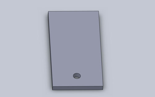
Swivel Plate
- Length: 457.2mm
- Width: 304.8mm
- Thickness: 25.4mm
- Swivel Hole Diameter: 30mm
- Swivel Hole Along Length; 50mm from Edge
- Swivel Hole Spacing Along Width: Centered
- Support Hole Diameter: 12mm with 20mm dia 13 deep countersink
- Support Hole Rectangle: 30mm x 55mm
- Support Hole Rectangle Spacing: Around a corner, 150mm apart center to center.
- Support Hole Notes: The Support holes must be positioned such that the blade is centered at the vise. The blade should be centered at the vise so that angled cuts are facilitated in both directions (angling to both left and right). The Support holes should also leave enough space between the Shaft Blocks such that a thrust washer and clamping shaft collar can fit in between (and be easily maintained).
- 2D Image
- 3D CAD STP
- 2D Fabrication Drawing PDF
- 2D Fabrication Drawing DXF
