Torch Table Intro
Introduction
This is the open source development page for an industrial duty acetylene or plasma torch table. The table is readily adaptable to industrial duty routing. Accuracy is not sufficient for circuit fabrication. Cost of the table is about $1500 for materials, and we aim to produce these tables for an additional $500-1000 in labor costs for a total of $2000-2500. Present motivation behind this is rapid fabrication of The Liberator CEB Press.
Torch Table Design
Our development log is here.
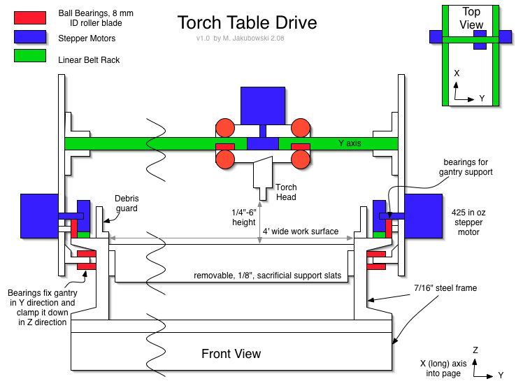
Here is an updated design schematic for a torch table. The drive is obtained with stepper motors and rack-and-pinion style direct drive with a 1" pulley. Using 425 in oz stepper motors, this allows for direct coupling and ~50 pounds of force delivered to move the gantry. Linear bearings and ball screws were replaced with rack-and-pinion drive due to cost considerations. Using direct rack and pinion drive, amazing accuracy is possible: theoretical 2/1000 of an inch for a 1 inch pinion gear with 1/8 stepping. The limiting factors will be straightness of the guide rail (1 1/4" cold rolled steel rod) and resolution of the pinion gear.
Notable design goals:
- 1/32" accuracy is sought for general acetylene torch cutting (or plasma cutter) applications
- Ball bearings ride directly on guide rail on the drive side
- Bearings ride directly on structural metal on the non-driven side
- Direct coupling of stepper motor to metal rack via a single pulley; no gearing involved
- Stepper motor speed: 10 RPM for ~30 inch per minute (IPM) motion with ~1 inch diameter pulley
- Fast rapid motion should be possible, 100 RPM for 300 IPM
- Traction of rack-and-pinion drive is obtained via the weight of the gantry
- Gantry weight: ~40 lb
- Lowest bearings in diagram below provide additional clamping in the Z direction, if needed
- Update: this is eliminated; check detail drawings below
- Frame is 6" wide U-channel, 7/16" thick
- 4'x8'x1' working object dimensions
Initial Designs
Y axis drive detail:
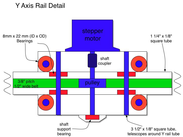
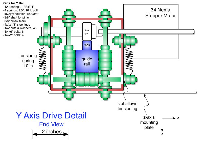
- Y axis motion is on a 1 1/4"x1/8" square tube as the rail, with a surrounding, telescoping 4"x6"x1/8" tube:
- Two telescoping tubes with bearings between them on all 4 sides function as a low-tech linear bearing
- 4 foot working object width
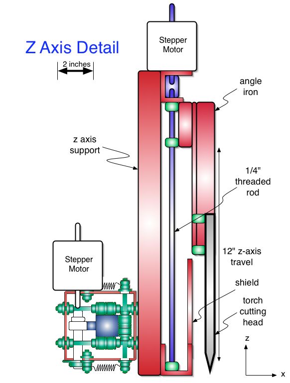
Z axis detail:
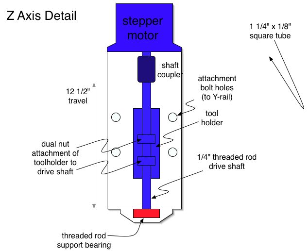
- 1 foot working object height
- Simple 1/4" threaded rod for drive
Design Details
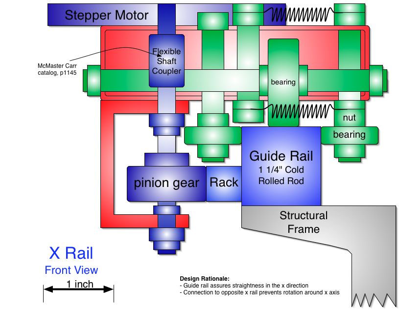
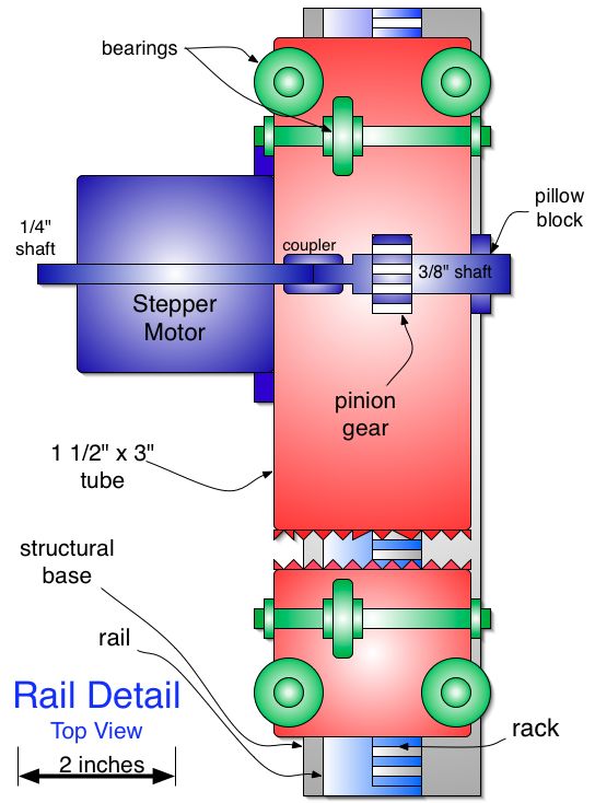
The initial concepts above have been refined to the following detail for the main precision rail. The red part is a rectangular tube 1 1/2"x3"x1/8".
Design rationale:
- Traction for the rack and pinion is obtained by gravity through the weight of the gantry and drive system
- Long-axis alignment is secured by the main guide rail, with 4 guiding ball bearings in the long direction (x)
- The axis for the pinion gear is supported on both ends
- Direct coupling of motor to gear is utilized
- 10 rpm of stepper motor yields 30 inches per minute travel - the max desired speed for cutting with an acetylene torch
- Rapid travel of torch ~300-600 inches per minute
- Pulley radius = 1 inch; circumference ~3 inches
- Driving torque is 425 in oz yields about 50 pounds of force for a pulley radius = 1/2 inch
- Gantry weight ~40 lbs, so approximately 1 g acceleration is possible
- Pitch of rack and pinion is 20 teeth per inch
- 200 step stepper motor is driven with 1/8th steps for theoretical 2 thousandths of an inch resolution in the x direction
- Straightness of guide rail will be the limiting factor
X Rail Detail, Front View
X Rail Detail, Top View
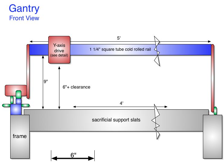
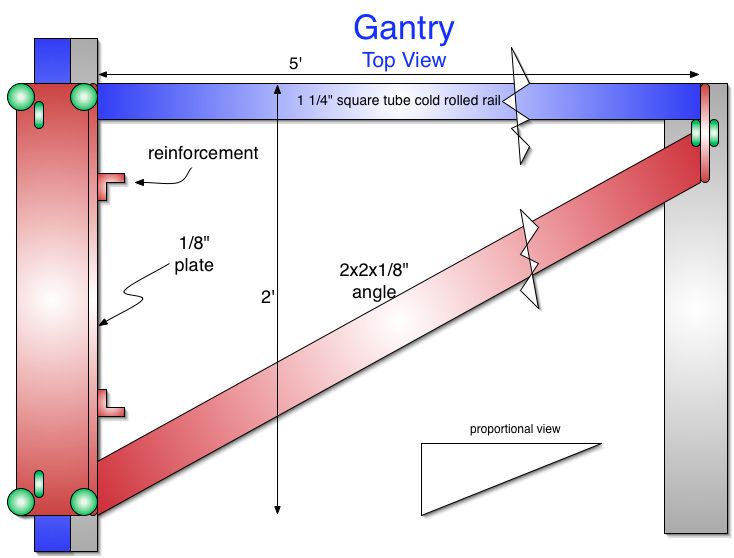
The assembly on the bottom left is the guide rail system detailed in the above 2 pictures. The gantry that carries the torch head consists mainly of the same type of guide rail as found for the long exis (x axis).
Gantry Front View
Gantry Top View
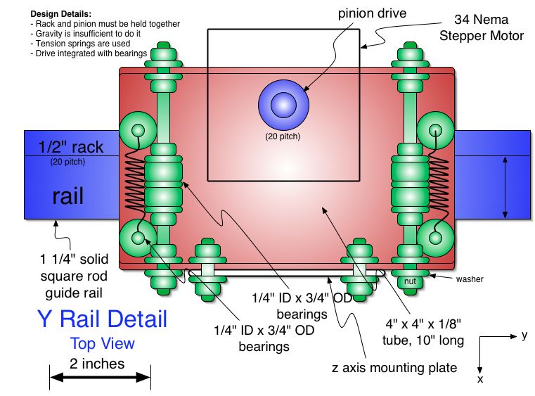
Y Rail Detail
The y rail is the blue part of the above 2 diagrams. The detail of the y-direction drive is shown below:
Y Rail End View
Z Axis Detail
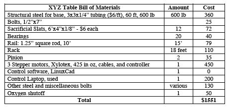
Bill of Materials
Details:
- Rack from Standard Steel Specialties. Quick response, great price on the rack.
- Pinion from McMaster.com, item 5172T12
- Xylotex motors and controller - [1]
- Bearings from vxb.com - [2]
- Small bolt prices at boltdepot.com - [3]
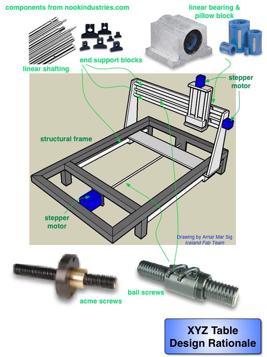
XYZ Table Preliminary Design
The specifications development for a robust and scaleable machine is under development here. The prototype specifications for a torch table application will be developed on this page.
The basic design follows.
Using ball screws and linear bearings appears to be the easiest method. Present research indicates that profile guide rails are twice as cheap for the accuracy required, so this will be redesigned.
Compare this to gear drive and linear rails, which appears to be more complicated in terms of drive components.
Note: you can find prices for linear guide rods and bearings at vxb.com.
Development Evolution
This section shows other options considered.
Torch Table Implementation
Specifications:
- .01 inch accuracy
- Precision acme rod
- Profile rail guides
Motors: [4]
- Nema 23 Double Stack/Double Shaft Bipolar Stepper Motor, Flats ground on each end
- 269 inch lb holding torque on main axis
- Rated Current - 2.8A/phase
- Shaft width - .25 inch
Controller:
- Direct coupling to precision acme rod
Bill of Materials for a Simple Prototype
- It appears that the Xylotex drive is applicable to large torch tables. Here is one that Xylotex told me uses their controllers and motors.
- $425 for motors and controllers
- Ball screw 5966K26 at McMaster Carr, $1.26/inch, and $25 for each ball nut - $125 per 6 foot run
- 90% mechanical efficiency compared to 30% for acme screw
- $250 for x axis if 2 screws, $125 for y axis (1 screw), $50 for z axis
- End blocks are extra
Here is a parts list:
- Compare 425 in oz motors to [269 in oz motors].
- Compare 4 axis kit, $400.
- See discussion on threaded rod vs. acme and precision acme.
- Good discussion on drive options from Solsylva
Instructables References
Search Instructables.com for CNC projects. There is a load. The people should be tapped for review. Just sign up and send authors an email.
- http://www.instructables.com/id/SDPT6W9F3HY3SLR/
- CNCZone hath lots of DIY implementations - [5]
- http://www.instructables.com/id/3-Axis-CNC-Router---60x60x5---JunkBot/
- Solsylva has plans for 3 axis tables, 2'x5' for the largest
ShopBot
Rack and Pinion Calculations
An interesting, low cost positioning system for low precision (0.01") machining (such as acetylene torch tables) consists of belt-drive rack and pinion.
Calculations:
- Typical motors have 0-1000 RPM and 200 steps
- A drive pinion of 1 inche diameter means 3 inch/200 = 15/1000 of an inch step resolution
- For a 2 inch drive wheel (recommended), this is 3/100 resolution, which is sufficient
- We need only 1/16 resolution, and we have twice that resolution with this system
Look for parts to match:
- McMaster Carr part 6486K129 - 20 mm wide, 280 cm long (9+ feet) Power Grip belts - $52.50
- 2.2 inch drive wheel - $43, would give 35/1000 step resolution
- McMaster Carr - item 7959K29, 3/4 inch rack-and pinion type belting, $5.69/foot - $32 for 9 feet
- Or, part # 7959K26, 1/2 inch belting, 3/8 inch pitch, high torque applications, $3.59/foot
- Part 6495K15 is pulley, $20 for 2.1" pulley.
Timing Belt Data
- [6] has strength of .375 pitch, 1/2" belt as 675 lbf/in breaking strength - neoprene, nylon covered.
- MXL .08 pitch, 1/4 inch wide belt (McMaster Carr part #1375K39) has accuracy of 1/2000. Uses 20 tooth pulley, .5" diameter
- 1.6" circumference/200 steps would be 80/1000 accuracy
- Proposed .375 pitch belt has 1.9 diameter pulley of 16 teeth
- 1/200 of 1.9*pi - this yields 1/30" accuracy for full steps. I may want to set for up to 1/8 microstepping.
