UELVE MBC/v0.1
Jump to navigation
Jump to search
Basics
- A lightweight (200 kg) 3 occupant vehicle design that can be mostly DIY constructed.
- Although intended as an EU Category L7e "Heavy Quadricycle" it can also be the basis for a USA "NEV" or a pedal-car, or E-bike "pedal assist" motors installed.
- Dimensions 1.5 x 3.1 x 1.1 metres for a front surface area of approx 1.5 sq. metres
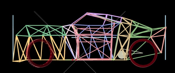
- Geodesic Frame skeleton is bamboo and PVC pipes connected together with 3D-printed software-generated "Nodes", which are then entirely encased in Expoxy Resin and Fibreglass, Kevlar, Hemp, Flax or other high-strength cloth layers.
- Double wishbone suspension is expected to be fitted at the front, whilst the rear may be swing-arm, Double-wishbone or Macpherson. This revision uses swing-arms at the rear.
- Body panels are twin layers of Fire-resistant Non-woven Polyester with a hot-glued 4 layer latticework "Hobbycraft" 9x1mm bamboo frame inside (9x1mm is easily bendable) to create compound curves. Label-gun "barbs" every 50 mm on a grid spacing will pin the two polyester sheets at a regular 10mm spacing, and Soudal Fire-resistant Expanding foam injected into the gap. After 2 days foam curing the panels are surprisingly strong and very light.
Frame Concept
Blue pipes are 1m measure sticks. Note that the body takes whatever form we would like.
- Outer skin using the GABoats technique (Geodesic Aerolite Boats) - http://gaboats.com
- Inner frame using 3D-printed fibre-reinforced "nodes" connecting continuous-fibre-reinforced pipes on a Fibre_Reinforced_Pipe_3D_Printer or getting carbon-fibre, hemp-reinforced tubes (or even Bamboo), based on the Divergent 3D "Blade" car manufacturing concept https://www.youtube.com/watch?v=vPv7PwS50OE
- Epoxy-soaked cloth "wrapping" carried out on joints, if necessary, using the Calfee Design Bamboo bike technique. https://calfeedesign.com/what-is-in-calfee-diy-kits/
- Swappable Modular batteries using the Open_Source_Battery_Pack
CAD Source Code
- git clone http://lkcl.net/vehicle_3d/.git
Prototype 1 Build Procedure
build log on endless sphere https://endless-sphere.com/forums/viewtopic.php?f=34&t=118802&p=1747637#p1747637
- Use PVC and bamboo frame members
- Wrap corners in epoxy-impregnated tape
- Wrap the length of tube bodies in epoxy-impregnated tape as needed for additional structural integrity
- For attachment points to metal components, embed metal mounting interface plates/mounts/components in epoxy-impregnated tape just like the corners to attach firmly to the underlying skeleton
Skeleton Frame Phase
BOM
estimated
- 300 metres bamboo canes between 8 to 13 mm diameter, or 300 metres PVC or other pipe or straight sticks up to 13mm. (structural strength is non-critical)
- 200 metres OD 21.5 mm ("Floplast") PVC waste pipe, ID 19.5 mm
- 500 metres 25mm width "Painter's" Masking tape
- 15 20g tubes of rubbery glue (Loctite Extreme, red tube - not Loctite Extreme Epoxy!). do not use hot-glue unless upgrading the 3D-printed nodes to PolyCarb or PETG: PLA deforms at only 60C. do not use strong epoxy or superglue
- 3 tubes Araldite Epoxy
- 5 kg PLA for 3D printing of "Nodes"
Tools
- 3D printer with 0.8mm nozzle, set layer height of 0.6 mm and 0.2mm "support towers", full coverage. Nodes are complex.
- Usual pliers and files for removing 3D support
- Full wrap eye protection (from high velocity 3D print support material during removal phase: it can get behind your eyes and start scratching)
- Hacksaw and Mitre (90 degree angle cutting)
- Sharp pencil
- 1 metre metal ruler and tape measure
- A4 printer, scissors
- 25 metres string (for tensioning). garden twine is sufficient.
Assembly advice
- Measure twice cut once!
- Cutting accuracy on pipes to around +/- 0.15 to 0.2 mm is pretty crucial. The geodesic frame shape amplifies errors which causes cascading problems that require partial disassembly to correct (hence the rubbery glue and masking tape instead of strong rigid epoxy or cyanoacrylate).
- Use the 3D CAD to create 2D screen-shots then draw Node and Pipe numbers on them. As each Node is 3D printed place the same Node number on it, written on masking tape. Print out pipe connectivity listings and cut them into strips that are taped onto the pipe during the cutting phase. Be very strict and patient here because there are 135 Nodes and around 400 pipes to assemble.
- Use the 3D CAD to zoom in onto Nodes in order to get their orientation correct. Sometimes the 2D A4-printed screenshots can be sufficient, but some Nodes are very similar. Make absolutely certain that the angle in all three axes is orientated to within under 2-3 degrees: greater than that results in pipes moving out of position and not seating correctly, and an error-cascade begins. If necessary cut all tape free from all pipes on a node, scrape off the rubbery glue then reglue and retape. Do not attempt to remove a Node from in the middle of an assembly.
- Pipes must be cut dead flat at 90 degrees. Use a file to ensure uneven ends are level: cutting is best done using a Mitre, circular bench saw, or even better a hand-hacksaw held in a cutting jig. It is best to slightly overcut (0.25 to 0.5 mm) then file down, although this can add significantly to build time. Do not attempt to use "undercut" 13 mm OD pipes, or if risking doing so add layers of thin cardboard glued in the seat of the Node in order to get its length back up. This trick will not work with the PVC pipes: there is a 19 mm "inset" on the Node which fits inside the 21.5 mm pipe. Undercut pipes are best put aside and used elsewhere in a shorter location.
- Start from a flat fully-triangulated base of parts then when going vertical locate 3 pipes onto one node and create tetrahedra on th3 fklat base. Use the Node seats as an accurate guide as to direction the pipe needs to go. Once one tetrahedra is created find another right next to it and asssemble that. Do not attempt to assemble from the outside inwards (and try to meet in the middle), work from one side to the other or from the middle to the outside: climbing *inside* the frame to glue-and-tape is very tricky.
- If when it comes to putting in single pipes towards the near-completion of an assembly there is a gap that cannot be bridged by using the masking tape to "pull" the pipe at both ends, use string wrapped carefully between other pipes on the same node at both ends, tie tightly then use another piece of bamboo to prise the twine apart, or use more twine, tying that to other nodes in the same plane to get heavy tension and push the gap shut. Be extra careful as this is where mistakes cascade and get noticed.
- The entire frame is extremely light (under 10 kg) at this stage: turn it upright or upside-down to make access easier, as needed.
Construction order
- Bonnet
- front
- dashboard
- floor and floor support
- Driver seat box
- "Back" box (behind occupants)
- Roof
- Rear frame
- Bumper
- Doors
Construct in 4 subassemblies:
- Bonnet, front, dashboard and 1/4 of the floor (assemble whole floor, al9ng with floor support; brace - double-up the bamboo with epoxy - then separate at the footwell line)
- Driver seat-box, "Back" box on floor, then brace around the Driver seat-box and separate another 1/4 of the floor
- Roof and top section of the "Back box"
- Rear frame continuation of the remaining "Back box" and add bumper
The subassemblies may be tightly taped to each other for checking rigidity and overall assembly correctness. After the Cloth-Resin Phase, bolt-holes will be drilled through, metal spacers inserted and epoxied in, so that the four sub-assemblies can be bolted together with Castle or Nylon lock-nuts.
Videos
https://www.youtube.com/playlist?list=PLBtNqZjUZB81KyRPnMHSmX-vF8i7h5kcA

