PVC Pipe and Fittings Library
Pipes
The dimensions of the PVC pipes can be found here PVC_Pipe. Wikipedia on Nominal Pipe Size (NPS) [1],
We will use following guide line for position of a pipe: put one end (base) of the pipe onto the x-y plane. The center of the base has coordinate (0,0,0). The other end points to the positive direction of the z-axis.
Rationale: This is the same way FreeCAD places a new cylinder. We mimic the FreeCAD behavior for UI consistancy.
The default pipe length is 1ft. This is an arbitrary choice. When I use a macro, it will store the last length used by the user.
Elbows
Useful links: [2]
90° - elbows
Described by 3 dimensions: pipe size, schedule, G,H,M. Other dimensions are derived from NPS pipe-dimensions.
One can create 90° with alpha°-elbow macro. Just set alpha=90° and J = H. I do not know why my parameter list uses "H" for 90°-elbows and "J" for other elbows.
alpha° - elbows
alpha, pipe size, schedule, H,J,M. Other dimensions are derived from NPS pipe-dimensions.
Notations
- O.D. - outer diameter.
- Average I.D. - average inner diameter (why average?). This dimension determines the size of the pipe.
- Min. Wall - thickness of the pipe wall.
- Schedule - determines (indirectly) the thickness of the wall.
Notes
"O.D." = "Average I.D."+2"Min. Wall"
Tees
Described by
G, G1, H, H1, L, M, Some other dimensions are taken from the pipe dimensions.
Gallery
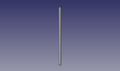
SCH80 1" PVC pipe - size:4kb - FreeCAD -File:Pvc-pipe-test.fcstd,
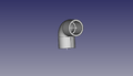
90°-elbow test file - size:17kb - FreeCAD -File:Pvc-elbow-90-test.fcstd,
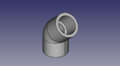
alpha°-elbow test file. Here alpha° is 45°. - size:19kb - FreeCAD -
,

Tee test file - size:24kb - FreeCAD -File:Pvc-tee-test.fcstd

Coupling test file - size:12kb - FreeCAD -File:Pvc-coupling-test.fcstd


Macros
Macros are now in a git repository [3]. The elbow macro depends now on other files. See README.md for installation instructions.
Pipes
To create Pipes 40 and 80 Schedule PVC pipes File:Create-pipe.fcmacro.

Elbows
To create an 90° elbow, run File:Create-elbow-90.FCMacro with parameters POD, PID, G, H, and M from a table. To create an elbow with an arbitrary alpha from 0° to 180°, run File:Create-elbow-alpha.FCMacro with parameter alpha, POD, PID, H, J, and M from a table.
This macro depends now on other files from [4].


Tee
Run File:Create-tee.fcmacro and select a part from the table.

Coupling
Run File:Create-coupling.fcmacro and select a part from the table.

How to create a pipe macro
Steps to create GUI: The original instruction are taken from [5] but I (Ruslan) have problems with them. I adjusted them to FreeCAD.
- Create with QT Designer a Dialog based on QDialog class. Save the name for example add-nps-pvc-pipe-dialog.ui.
- Convert add-nps-pvc-pipe-dialog.ui to python code running
- pyside-uic add-nps-pvc-pipe-dialog.ui -o pipe-dialog.py
- or call
- pyside-uic --indent=0 add-nps-pvc-pipe-dialog.ui -o pipe-dialog.py
- to use tabs as indention.
- If you use the FreeCAD macro editor, pay attention that the indention of pyside-uic and of the editor are the same.
- Insert content of the methods setupUi(self, Dialog) and retranslateUi(self, Dialog) from pipe-dialog.py (How can I insert here a block of python code?) into your macro file.
FAQ
- Do we really want to 3D-print pipe fittings? Somehow I have doubt about mechanical properties of the 3D-printed products.
- Yes. For high pressure applications - 300 PSI - we would have to be very careful. For low pressure, such as 5 PSI, it's not a problem. Eventually, we want to refine printing techniques where our fittings can do what standard schedule 80 ABS fittings can do.