PVC Pipe and Fittings Library
Basics
This is a library of all the current PVC Pipe and Fittings that have been made in freecad for OSE. Many fittings can be created using #OSE Piping Workbench.
Pipes
The dimensions of the PVC pipes can be found here PVC_Pipe. Wikipedia on Nominal Pipe Size (NPS) [6],
A pipe is described by its outer diameter OD, its wall thickness Thk and its height[1] H.

Workbench
To create a pipe, click  in OSE piping workbench.
Adjust CSV pipe.csv in tables directory within workbench directory to add new pipe dimensions to the list.
in OSE piping workbench.
Adjust CSV pipe.csv in tables directory within workbench directory to add new pipe dimensions to the list.


Notations used by others
- O.D. - outer diameter.
- Average I.D. - average inner diameter (why average?). This dimension determines the size of the pipe.
- Min. Wall - thickness of the pipe wall.
- Schedule - determines (indirectly) the thickness of the wall.
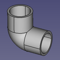
Elbows
Useful links: [7]
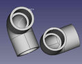
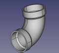
Elbows
An elbow is described by an angle alpha, outer pipe diameter POD, inner pipe diameter PID, H, J, M.

Workbench
To create an elbow, click  in OSE piping workbench.
To add new elbows, adjust elbow.csv in tables directory within workbench directory.
in OSE piping workbench.
To add new elbows, adjust elbow.csv in tables directory within workbench directory.


Couplings
A (general) coupling is described by dimensions: POD, POD1, PID, PID1, L, M, M1, N. The dimensions POD1 and PID1 are not from a official specifications. They are derived from pipe size and schedule. In a reducer coupling, the pipe dimensions on one side POD and PID differ from on the other side POD1 and PID1.

Workbench
To create a coupling, click  in OSE piping workbench.
To add a new coupling to the part list, adjust coupling.csv in tables directory within workbench directory.
in OSE piping workbench.
To add a new coupling to the part list, adjust coupling.csv in tables directory within workbench directory.


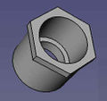
Bushings
Important: There was a bug in workbench with version until 03. March 2018, where PID was used instead of POD.
A bushing is described by dimensions N, L and pipe dimensions. As pipe dimensions we use POD, PID1, and POD1.

Workbench
Important: There was a bug in workbench with version until 03. March 2018, where PID was used instead of POD.
To create a bushing, click  in OSE piping workbench.
To add a new coupling to the part list, adjust bushing.csv in tables directory within workbench directory.
in OSE piping workbench.
To add a new coupling to the part list, adjust bushing.csv in tables directory within workbench directory.


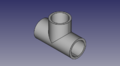
Tees
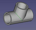
Almost General Tees
A tee is described by parameters G, G1, G2, H, H1, H2, M, M1, and pipe dimensions. As pipe dimensions we use POD, POD1, PID, and PID1.

Workbench
To create a tee click  in OSE piping workbench.
To add a new tee to the part list, adjust tee.csv in tables directory within workbench directory.
in OSE piping workbench.
To add a new tee to the part list, adjust tee.csv in tables directory within workbench directory.


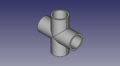
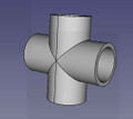
Cross
Almost General Cross
A cross is described by dimensions G, G1, G2, G3, H, H1, H2, H3, M, M1, and pipe dimensions. As pipe dimensions we use POD, POD1, PID, and PID1.

Workbench
To create a tee click  in OSE piping workbench.
To add a new cross to the part list, adjust cross.csv in tables directory within workbench directory.
in OSE piping workbench.
To add a new cross to the part list, adjust cross.csv in tables directory within workbench directory.


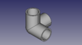
Corners
An corner is described by dimensions G, H, M and pipe dimensions. As pipe dimensions we use POD and PID.

Workbench
To create a corner, click  in OSE piping workbench.
To add a new corner to the part list, adjust corner.csv in tables directory within workbench directory.
in OSE piping workbench.
To add a new corner to the part list, adjust corner.csv in tables directory within workbench directory.


Genaerated Library Parts
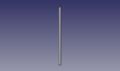
SCH40 1" PVC pipe - size:5kb - FreeCAD -File:Pipe-test.fcstd,
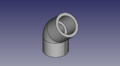
Elbow test file. Here alpha° is 45°. - size:21kb - FreeCAD -File:Elbow-test.fcstd,
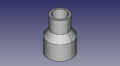
1"-1/2" coupling test file - size:17kb - FreeCAD -File:Coupling-test.fcstd
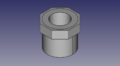
1"-1/2" bushing - size:21kb - FreeCAD -File:Bushing-test.fcstd
1" tee test file - size:28kb - FreeCAD -File:Tee-test.fcstd
1" cross test file - size:34kb - FreeCAD -File:Cross-test.fcstd
1" outer corner test file - size:30kb - FreeCAD -File:Corner-test.fcstd
Library of STEP Downloads from McMaster Carr
Comparable in size to generated parts - except for some parts which are way too heavy.
1" PVC Elbow - size:19kb - FreeCAD -File:1"-pvc-elbow.fcstd,
Note slight difference compared to generated - 0.15" wall for generated, 0.12 for downloaded.
1" PVC Tee - size:25kb - FreeCAD -File:1"-pvc-tee.fcstd,
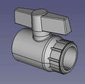
1" PVC Valve - size:500kb - FreeCAD -File:1"-pvc-valve.fcstd,
1"-3/4" PVC Bushing - size:13kb - FreeCAD -File:1"-34"-reducer.fcstd,
1" PVC Cross - size:13kb - FreeCAD -File:1"-cross.fcstd,
2" PVC Elbow - size:157kb - FreeCAD -File:2"-elbow.fcstd,
- 2"-tee.jpg
2" PVC Tee - size:8kb - STEP -[1] - FreeCAD - File:2"-pvc-tee.fcstd
- 2"-tee-short.jpg
2" PVC Tee - Short Nonstandard - size:4kb - STEP -[2] - FreeCAD - File:2"-pvc-tee-short.fcstd
- 2"-3"-bushing.jpg
2"-3" bushing - size:161kb - STEP -[3] - FreeCAD - File:2"-3"-bushing.fcstd
- 3"-2"-reducer.jpg
2"-3" reducer. Note difference between a reducer and a bushing (last one) - size:161kb - Menards -[4] - FreeCAD - File:3"-2"-reducer.fcstd
- 3"-2"-reducer.jpg
2"-1" reducer. - size:10kb - STEP -[5] - FreeCAD - File:2"-1"-PVC-reducer.fcstd


OSE Piping Workbench

Implemented are:
- pipe
- coupling
- bushing
- elbow
- tee
- cross
- outer corner

Installation
In a Linux system
$ mkdir ~/.FreeCAD/Mod
$ cd ~/.FreeCAD/Mod
$ git clone https://github.com/rkrenzler/ose-piping-workbench.git
![]() Command line instructions work on Ubuntu 16.04
Command line instructions work on Ubuntu 16.04
Hint:For those new to Linux, always remember Linux is case sensitive. mkdir ~/.FreeCAD/Mod creates the mod directory inside of FreeCAD. this might already exist, and that is fine.
Remarks about the coupling code
To create a simple coupling or a reduced we internally use a more general coupling. This general coupling is described by 9 dimensions: POD, PID, POD1, PID1, X1, X2, N, M, M1. The dimensions POD, PID, POD1, and PID1 are derived from the pipe sizes. The are abbreviations of Pipe Outer Diameter and Pipe Inner Diameter. The dimensions X1 and X2 are not official dimension names.

The offset a1 is calculated in such a way, that the thinest part of the middle section is not thinner than the walls on of the both sockets. Lengths a2, a3, a4 and angle b1 are derived from the dimensions and are only used to calculate a1.
FAQ
- Do we really want to 3D-print pipe fittings? Somehow I have doubt about mechanical properties of the 3D-printed products.
- Yes. For high pressure applications - 300 PSI - we would have to be very careful. For low pressure, such as 5 PSI, it's not a problem. Eventually, we want to refine printing techniques where our fittings can do what standard schedule 80 ABS fittings can do.
- Also with things such as part baking/anealing, composite filaments, and SLA or SLS Printers, very durable parts can be made
See Also
Useful Links
- ↑ We use height instead of length in order to make a pipe similar to a FreeCAD cylinder. These particular choice of pipe dimensions make it more compatible with pipes from flamingo workbench.