Gear
Introduction
Gears, just like spurs and sprockets, are mechanisms used to transfer energy by rotary motion.
They can all be used to change the following:
- Speed of rotation
- Direction of rotation
- Amount of torque available to do work
Gears can be used to trade rotational speed for torque or vice versa. In other words, in gearing there is an inverse relationship between rotational speed and torque.
The Input gear, also known as the Drive gear, is connected directly to a motor (or the pedals on a bike) and drives the Output gear.
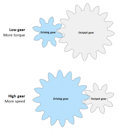
In lower gear, the Drive gear is smaller than the Output gear and for example rotates a bike wheel slower but with more torque to get you up a hill.
In higher gear, the Drive gear is bigger than the Output wheel and rotates the wheel with lower torque but faster rotational speed.
| Drive Gear | Output Gear | Torque | Speed | |
|---|---|---|---|---|
| Lower gear: | Smaller | Bigger | Stronger | Slower |
| Higher gear: | Bigger | Smaller | Weaker | Faster |
Contact Ratio
The contact ratio (ε) measures the average number of teeth in contact at all times. Mating gears should always have the same size teeth (the same parametric pitch.) The best contact ratio must be larger than 1.2 to ensure the ability to transmit high loads, offer rigidity to the transmission and allow for a silent and uniform operation.
Gear ratio calculation
The latest stable version of the Open Source Ecology Gear calculator is found here:
Gear ratio (GR) is the ratio between the rotational speeds of two mating gears. It can be be calculated with the following formulas:
GR = n1/n2 = d1/d2 = τ1/τ2 = ω2/ω1
where
n = number of teeth
d = diameter
τ = torque
ω = velocity
The number 1 following the symbol indicates that we are referring to the driven gear (or output gear). The number 2 following the symbol indicates that we are referring to the driving gear (or input gear). For example: n1 = number of teeth of the output gear. τ2 = the torque of the input gear.
Note that for the fraction containing velocity ω, the input is divided by the input, whereas this is reversed for the other fractions.
When selecting a Gearbox (also known as Gear Reducer, Speed Reducer or simply Reducer) for a motor, the Gear Ratio can be calculated like this:
Gear Ratio = Motor Speed/Required Speed
Then the New required torque must be calculated like this:
New Required Torque = Initial Required Torque/Gear Ratio
Gear ratio calculation examples
The images for the calculation examples below were generated by using this website: https://geargenerator.com
Two mating gears
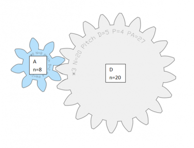
The gear ratio (GR) between the driving gear A and the driven gear D shown in the picture below is calculated as follows:
Gear ratio for gear A and D = number of teeth of D / number of teeth of A;
GR,AD = nD/nA = 20/8 = 2.5
Gear train with Idler gears
To calculate the total gear ratio of a gear train (a set of two or more connected gears), the gear ratios of each pair is multiplied.
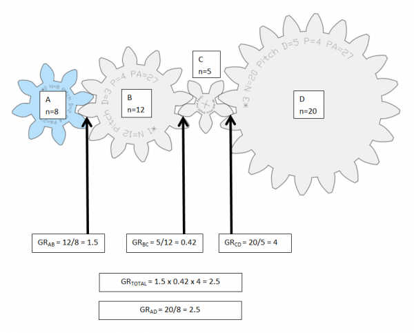
In other words, if we have a train of four gears, A, B, C, and D, (as in the image below) the total ratio is calculated by multiplying the gear ratio between
- A & B,
- B & C, and
- C & D, so that
GR,total = GR,AB x GR,BC x GR,CD = nB/nA x nC/nB x nC/nD = 12/8 x 5/12 x 20/5 = 2.5
However, this example can be calculated exactly as the one above it and the results are identical; GR,AD = 2.5. That is because all gears are connected to their own individual axis and because the Input gear A and the Output gear D have the same number of teeth as in the example above. The fact that none of the gears share an axis makes the gears in between the first and the last gear so called Idler gears. No matter the size or the number of Idler gears put in between the Input and Output gear, it will not affect the total gear ratio of the gear train. That is because each idler gear will be used as Input in one fraction followed by a fraction where the same gear is instead used as an Output so that it cancels itself out.
Compound gear train
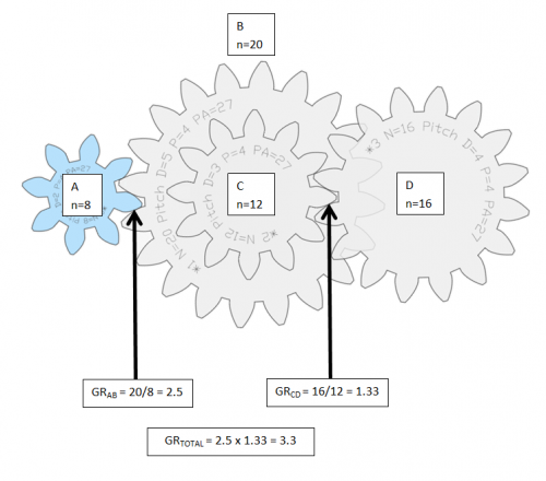
In this example, gear B and C share axis. Therefore the gears in between the Input gear and the last gear cannot be ignored as in the example above. Instead the gear ratio of each gear pair must be multiplied to calculate the total gear ratio: GR,total = GR,AB x GR,CD = nB/nA x nC/nD = 20/8 x 16/12 = 2.5 x 1.33 = 3.3
See also
External links
https://geargenerator.com (the gear images in this article were created using website.)


