Gear
Introduction
Gears, just like spurs and sprockets, are mechanisms used to transfer energy by rotary motion.
They can all be used to change the following:
- Direction of rotation
- Speed
- Torque
Gears are used to trade rotational speed for torque or vice versa. In other words, in gearing there is an inverse relationship between rotational speed and torque.
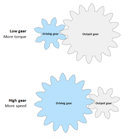
The Input gear, also known as the Drive gear, is connected directly to a motor (or the pedals on a bike) and drives the Output gear.
In lower gear, the Drive gear is smaller than the Output gear and for example rotates a bike wheel slower but with more torque to get you up a hill.
In higher gear, the Drive gear is bigger than the Output wheel and rotates the wheel with lower torque but faster rotational speed.
| Drive Gear | Output Gear | Torque | Speed | |
|---|---|---|---|---|
| Lower gear: | Smaller | Bigger | Stronger | Slower |
| Higher gear: | Bigger | Smaller | Weaker | Faster |
Types of Gears
The table below provides a comparison of a number of gear types. The parameters used are described below the table unless self-explanatory.
Gear parameter explanations
Axes condition
An axis is the cylinder which a gear is applied to. The axis condition describes how two axes for a mated gear pair are oriented relative to each other. There are three types of Axes conditions:
- Parallel: both axes which the two gears are attached to run parallel to each other.
- Intersecting: the theoretical center-lines going through the center of the two center holes of the gears intersect.
- Non-parallel and non-intersecting: the theoretical center lines of the axis are not parallel and do not intersect.
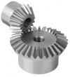
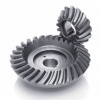
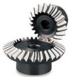
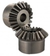
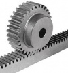
The possible axes condition for the gear types in the table above can be identified by picturing axes running through the center holes of the gears in the images.
Efficiency Range
No system is 100% efficient but losses in efficiency will require more input power for the motor driving the gears and possibly a more powerful and expensive motor to achieve the required torque. Efficiency range refers to the span between the typical minimum and maximum efficiencies for the respective gear types.
Ratio range
Gear ratio (GR) is the ratio between the rotational speeds of two mating gears. The Ratio range spans from the minimum appropriate gear ratio to the maximum.
Max Speed
Speed can either be measured in RPM (Revolutions per Minute) or in meters per second. There are low, mid, and high velocity gears:
- Low: <3 m/s
- Mid: 3 - 15 m/s
- High: >15 m/s
Max Load
Max load refers to the amount of torque that the respective gear types can deliver without breaking or wearing out quickly. Besides gear type, the max load will depend on the material and the size along with the Gear Module (explained further down in this article.) In the table above, gears of the same material, size and module is assumed.
Thrust Force prevention
Thrust force is unintentional force along the axis to which a gear is applied. Thrust forces can be mitigated by applying thrust bearings to axes.
Cost efficiency
Cost efficiency is tied to the simplicity of the design of a gear and in turn its manufacturability. Gears with more advanced design that are harder to fabricate will cost more.
Gear materials
Mated gears should be made from different materials to avoid abrasion and scoring.
Below are some common gear materials and their properties:
- Cast iron: low cost, low precision.
- Steel: high cost, high hardness and tensile strength
- Nylon: low cost, non-corrosive properties, not suitable for high load applications.
- Brass: low cost, high precision, not suitable for high load applications.
- Aluminum: low cost, not suitable for high load applications.
Contact Ratio
The contact ratio (ε) measures the average number of teeth in contact at all times. Mating gears should always have the same size teeth (the same parametric pitch.) The best contact ratio must be larger than 1.2 to ensure the ability to transmit high loads, offer rigidity to the transmission and allow for a silent and uniform operation.
Gear ratio calculation
The latest stable version of the Open Source Ecology Gear calculator is found here:
Gear ratio (GR) is the ratio between the rotational speeds of two mating gears. It can be be calculated with the following formulas:
GR = n1/n2 = d1/d2 = τ1/τ2 = ω2/ω1
where
n = number of teeth
d = diameter
τ = torque
ω = velocity
The number 1 following the symbol indicates that we are referring to the driven gear (or output gear). The number 2 following the symbol indicates that we are referring to the driving gear (or input gear). For example: n1 = number of teeth of the output gear. τ2 = the torque of the input gear.
Note that for the fraction containing velocity ω, the input is divided by the input, whereas this is reversed for the other fractions.
When selecting a Gearbox (also known as Gear Reducer, Speed Reducer or simply Reducer) for a motor, the Gear Ratio can be calculated like this:
Gear Ratio = Motor Speed/Required Speed
Then the New required torque must be calculated like this:
New Required Torque = Initial Required Torque/Gear Ratio
Gear ratio calculation examples
Two mating gears
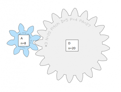
The gear ratio (GR) between the driving gear A and the driven gear D shown in the picture below is calculated as follows:
Gear ratio between gears A and D = number of teeth of D / number of teeth of A;
GR,AD = nD/nA = 20/8 = 2.5
Gear train with Idler gears
To calculate the total gear ratio of a gear train (a set of two or more connected gears), the gear ratios of each pair is multiplied.
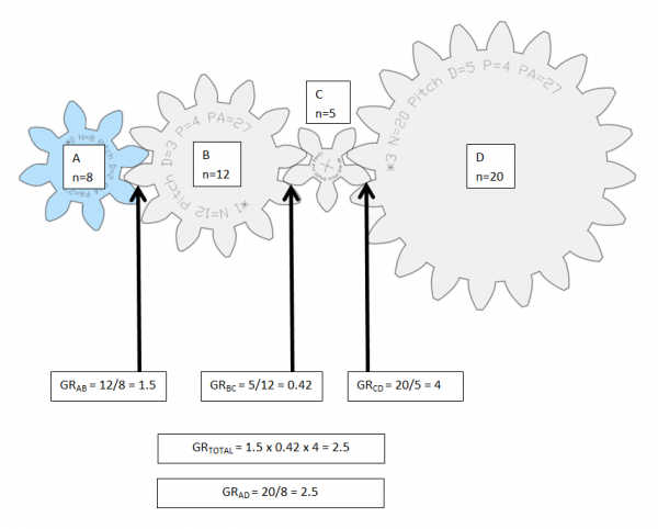
In other words, if we have a train of four gears, A, B, C, and D, (as in the image below) the total ratio is calculated by multiplying the gear ratio between
- A & B,
- B & C, and
- C & D, so that
GR,total = GR,AB x GR,BC x GR,CD = nB/nA x nC/nB x nC/nD = 12/8 x 5/12 x 20/5 = 2.5
However, all gears except the first gear (Driver) and the last gear (Output) can be disregarded and the results will still be the same; GR,AD = 2.5 (just like the example above with only two gears.) That is because all gears are connected to their own individual axis. The fact that none of the gears share an axis makes the gears in between the first and the last gear so called Idler gears. No matter the size or the number of Idler gears put in between the Input and Output gear, it will not affect the total gear ratio of the gear train. That is because each idler gear will be used as Input in one fraction followed by a fraction where the same gear is instead used as an Output so that it cancels itself out.
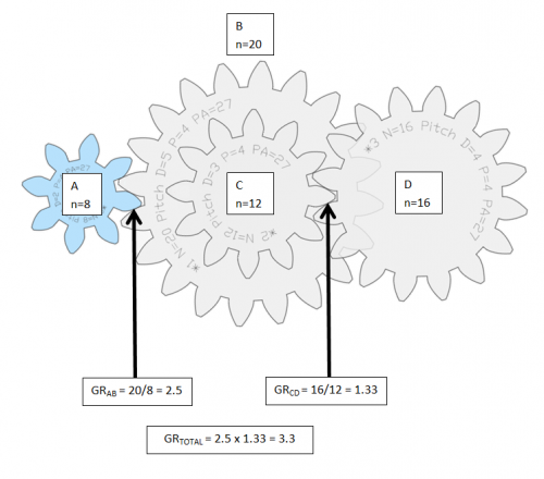
Compound gear train
In this example, gear B and C share axis. Therefore the gears in between the Input gear and the last gear cannot be ignored as in the example above. Instead the gear ratio of each gear pair must be multiplied to calculate the total gear ratio: GR,total = GR,AB x GR,CD = nB/nA x nC/nD = 20/8 x 16/12 = 2.5 x 1.33 = 3.3
See also
[List of Machine element calculators]
External links
https://geargenerator.com (the gear illustrations in this article were created using website.)
