CEB Prototype 1 Fab
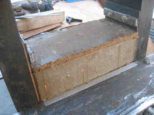
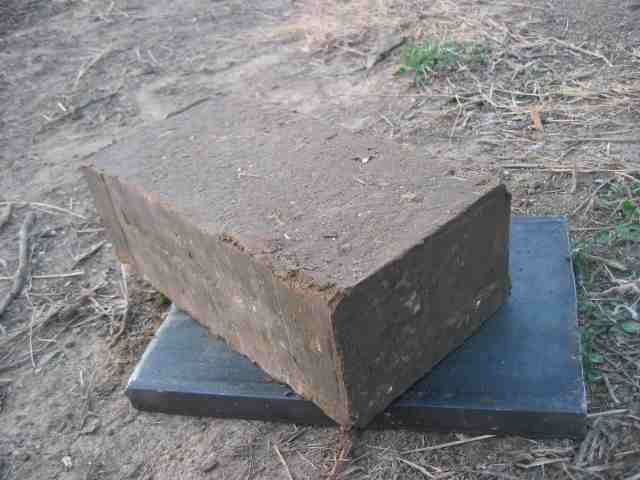
Here are most of the details for fabricating CEB Prototype 1.
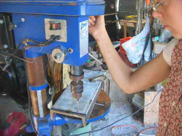
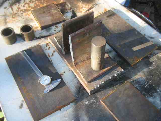
We start with raw metal. Drill holes in the structure pieces, 7/16" x 6 inch u-channel:
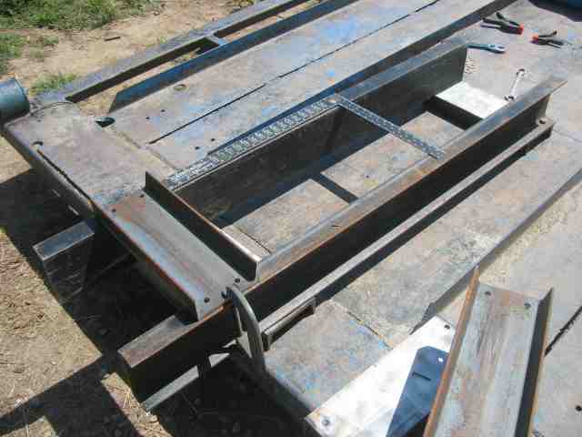
Begin putting the frame together:
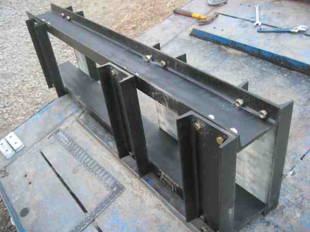
Use 1/2", grade 8 bolts, and the frame is complete:
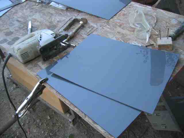
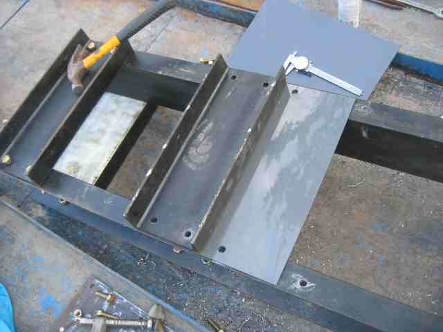
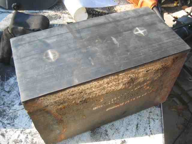
Cut Nylon 6/6 liner to size, and use it for abrasion resistance for the compression chamber:
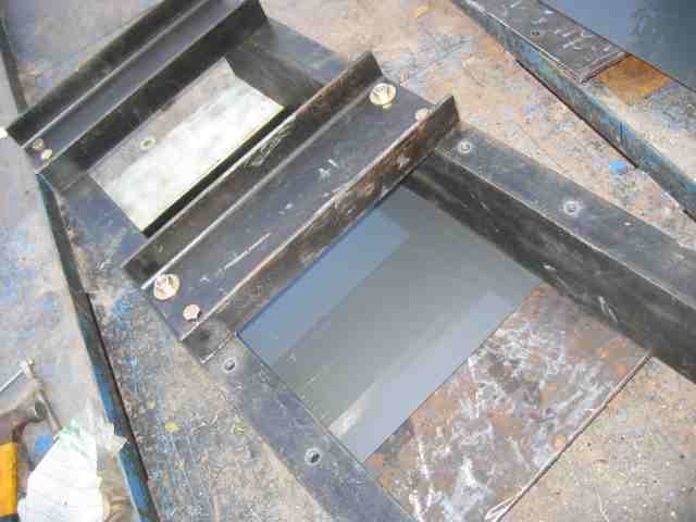
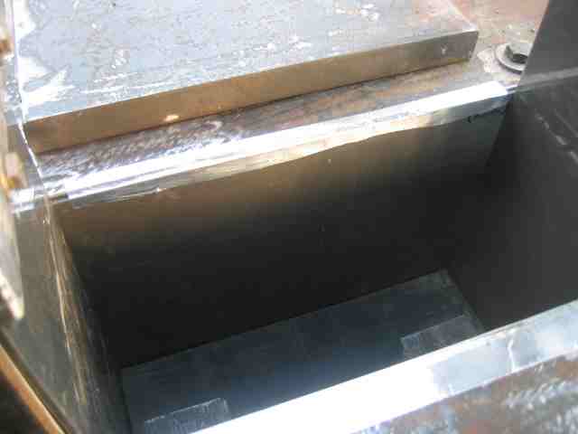
Install the Nylon liner in the compression chamber:
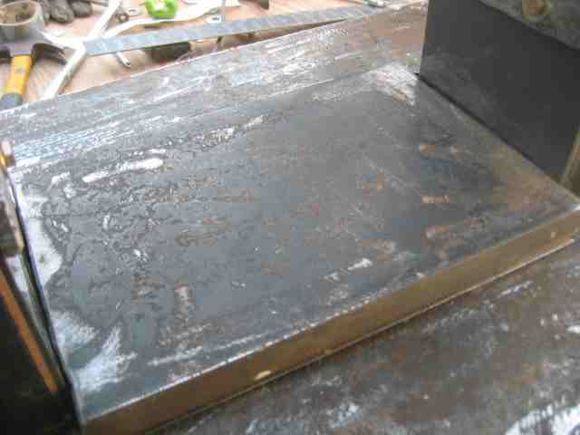
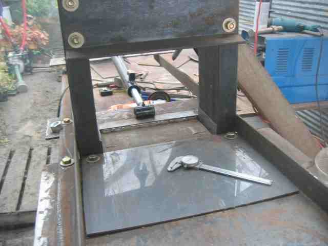
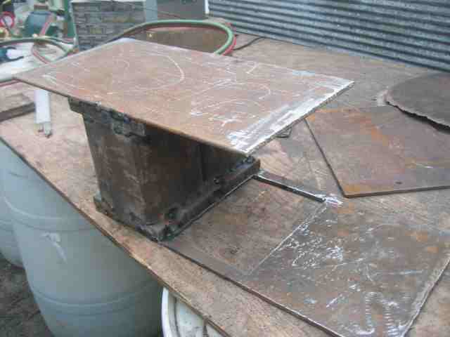
Add the plate for the compression chamber box, with the Nylon underneath:
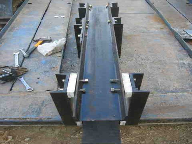
Put in spacers for the bottom of the frame, as the 5 inch cylinder that we used was fatter than 6 inches of the frame width:
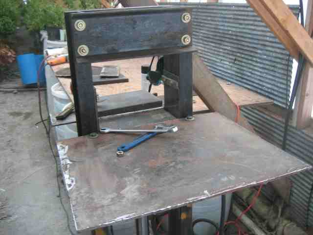
Assemble and stand the machine:
<object width="425" height="350"> <param name="movie" value="http://www.youtube.com/v/HAA--hZMqIA"> </param> <embed src="http://www.youtube.com/v/HAA--hZMqIA" type="application/x-shockwave-flash" width="425" height="350"> </embed> </object>
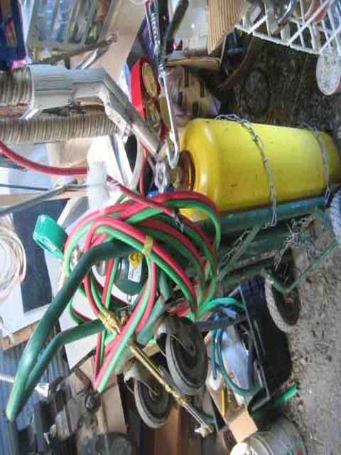
Take out the acetylene torch:
And slice up metal pieces for the pressing plate:
Grind and prepare pressing plate assembly:
<object width="425" height="350"> <param name="movie" value="http://www.youtube.com/v/PTbdqzi1zZM"> </param> <embed src="http://www.youtube.com/v/PTbdqzi1zZM" type="application/x-shockwave-flash" width="425" height="350"> </embed> </object>
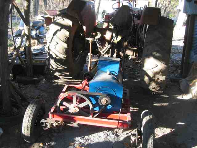
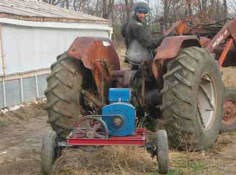
We used a 20 kW tractor power-take-off (PTO) genearator to feed the welder.
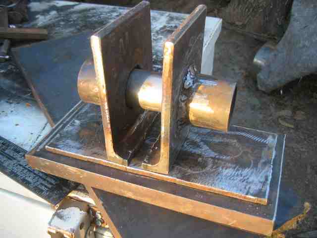
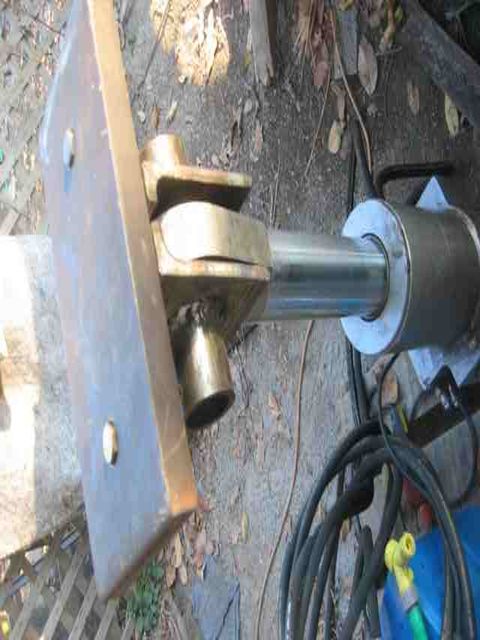
Here is the prepared pressing plate assembly with cylinder pin:
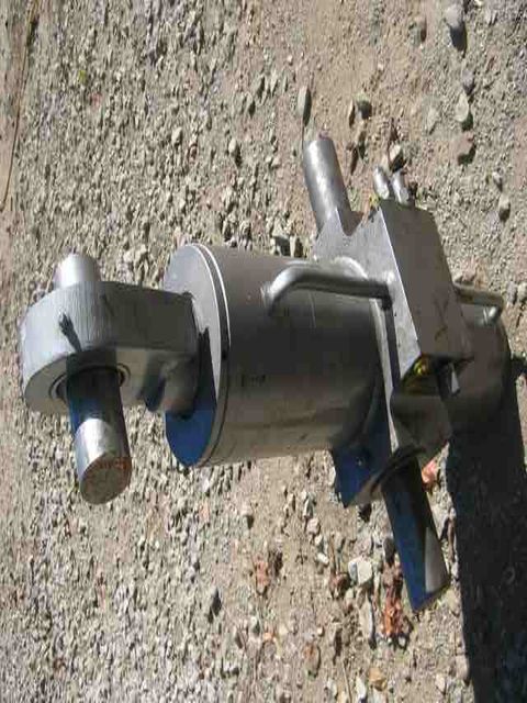
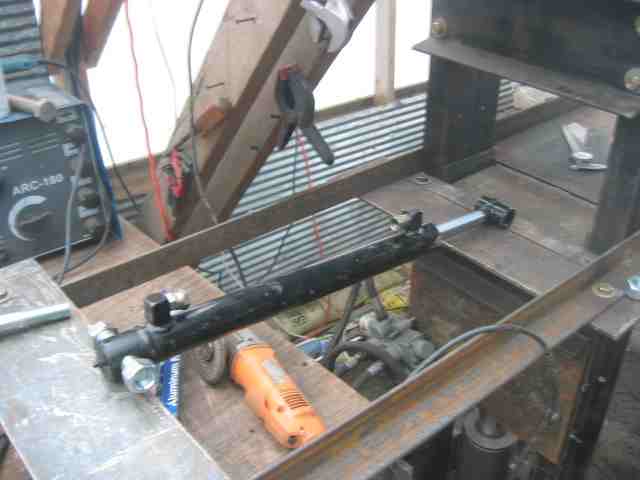
Add the 5 inch, 2.5 inch rod, ~20 ton hydraulic cylinder:
Fit the pressing plate assembly on the cylinder:
Prepare sides of the compression plate, so the compression plate assembly moves straight vertically:
<object width="425" height="350"> <param name="movie" value="http://www.youtube.com/v/HOlk4SH5aK8"> </param> <embed src="http://www.youtube.com/v/HOlk4SH5aK8" type="application/x-shockwave-flash" width="425" height="350"> </embed> </object>
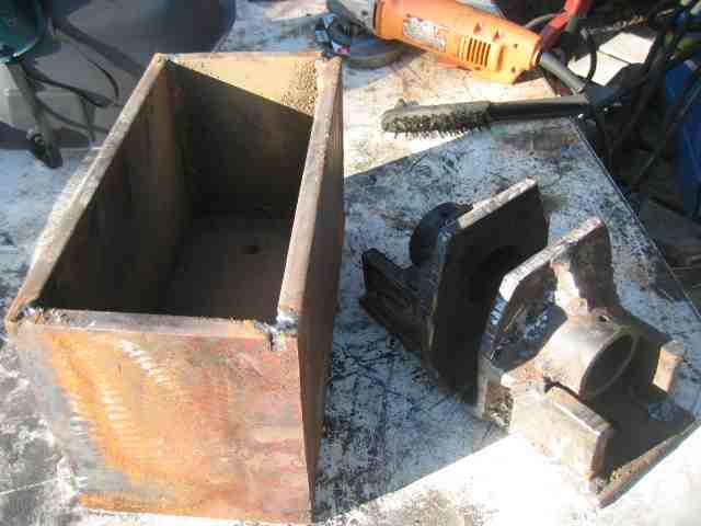
Here is the finished press plate and cylinder mount before assembly:
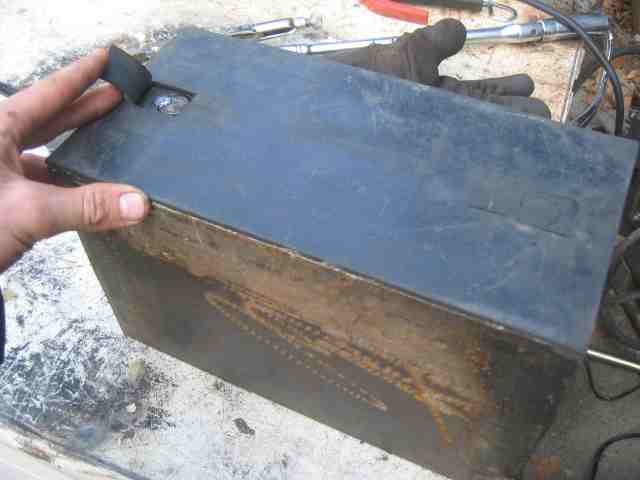
Here is the assembled press plate, with rubber liner on top:
Note how the two pieces are bolted together:
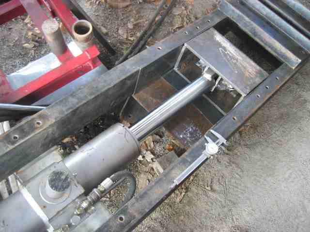
Now we fit the compression box assembly in the frame, attach the cylinder and hydraulics, and test motion of the cylinder:
<object width="425" height="350"> <param name="movie" value="http://www.youtube.com/v/2AF6h-WaFI0"> </param> <embed src="http://www.youtube.com/v/2AF6h-WaFI0" type="application/x-shockwave-flash" width="425" height="350"> </embed> </object>
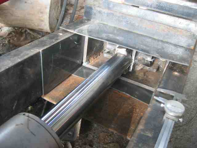
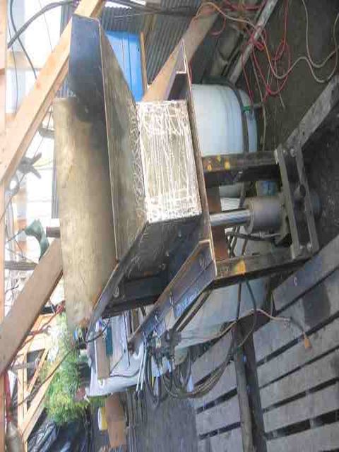
Now we fit the cylinder and press plate into the frame:
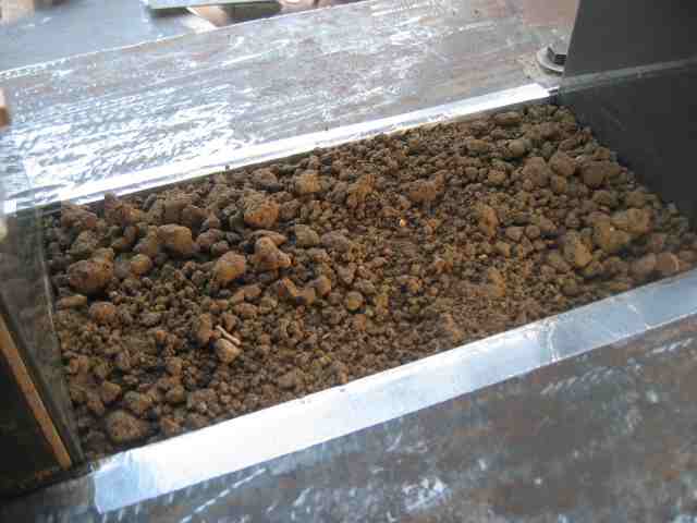
We close up the compression box:
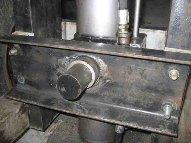
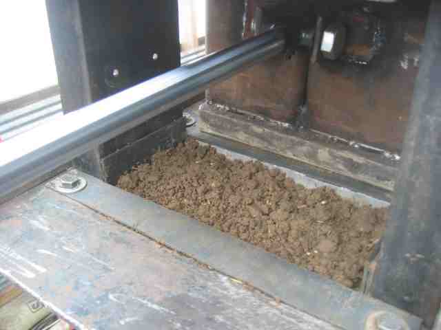
Here we show other details of mounting the cylinder in the frame:
