CEB Prototype 1 Fab
Here are most of the details for fabricating CEB Prototype 1.
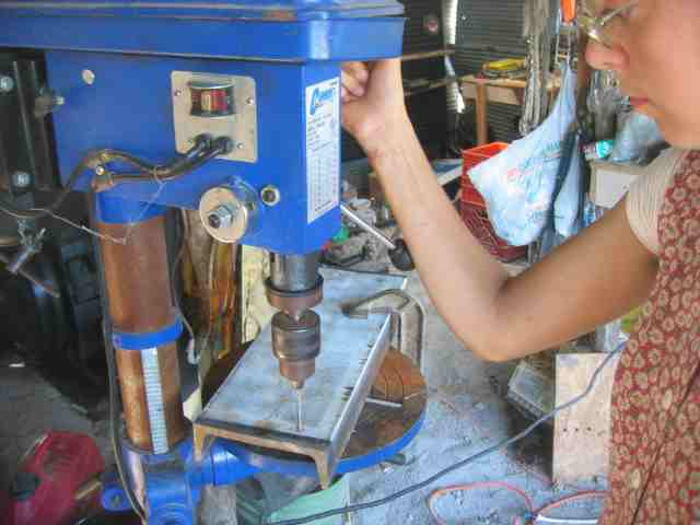
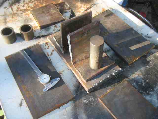
We start with raw metal. Drill holes in the structure pieces, 7/16" x 6 inch u-channel:
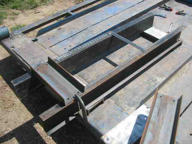
Begin putting the frame together:
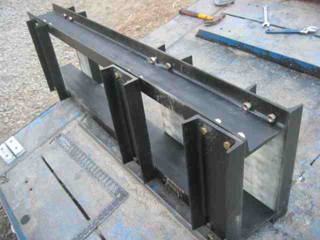
Use 1/2", grade 8 bolts, and the frame is complete:
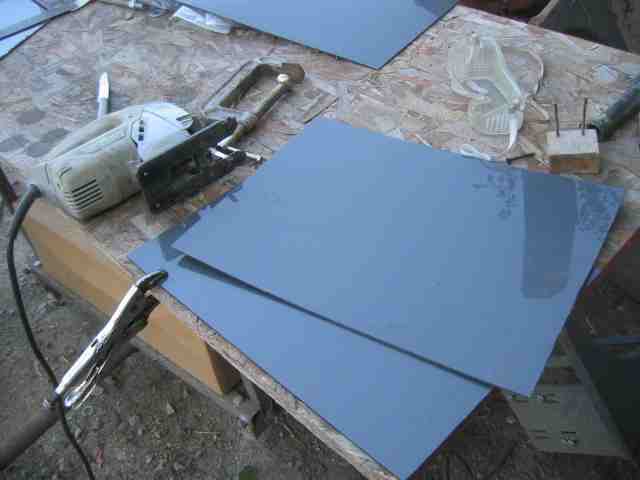
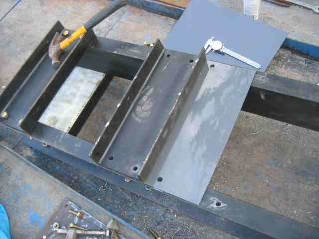
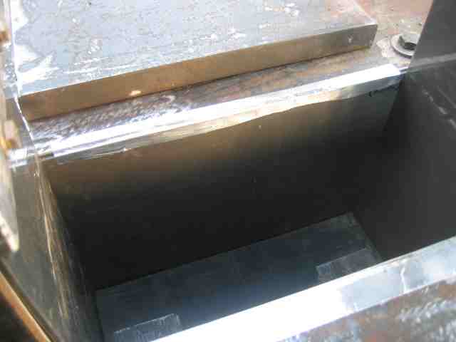
Cut Nylon 6/6 liner to size, and use it for abrasion resistance for the compression chamber:
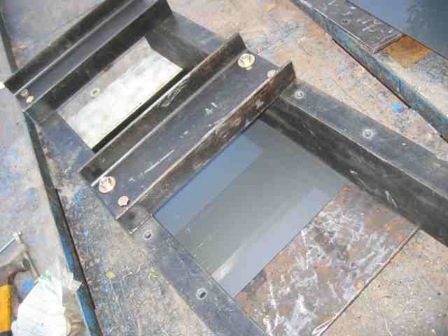
Install the Nylon liner in the compression chamber:
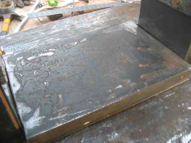
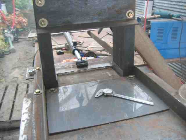
Add the plate for the compression chamber box, with the Nylon underneath:
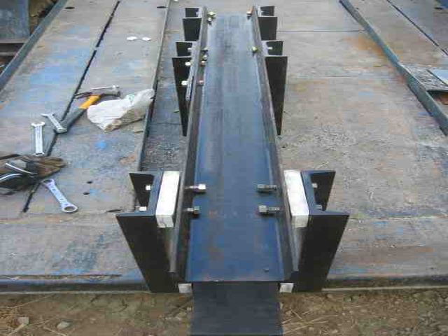
Put in spacers for the bottom of the frame, as the 5 inch cylinder that we used was fatter than 6 inches of the frame width:
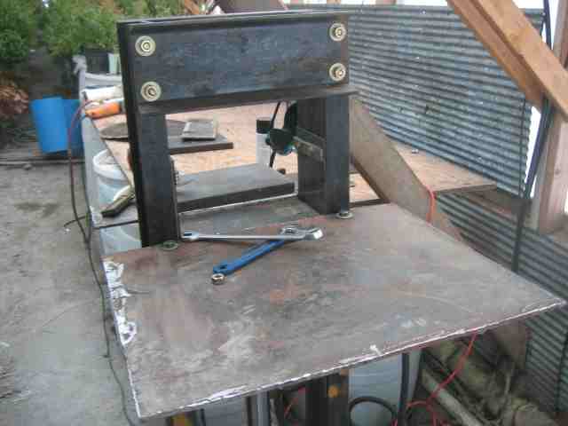
Assemble and stand the machine:
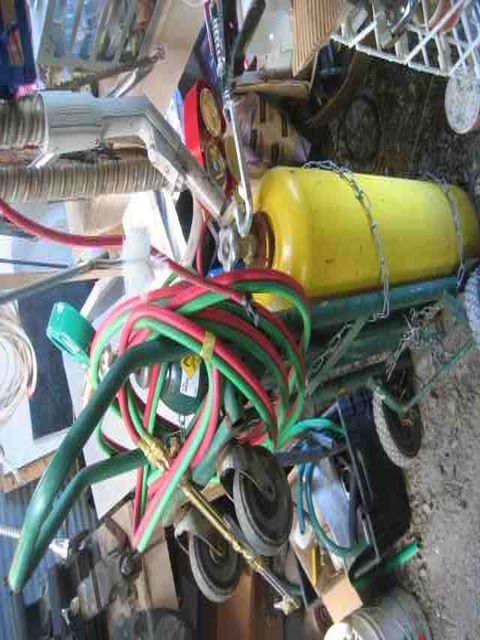
Take out the acetylene torch:
And slice up metal pieces for the pressing plate:
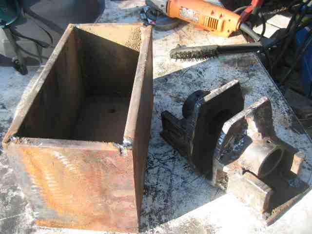
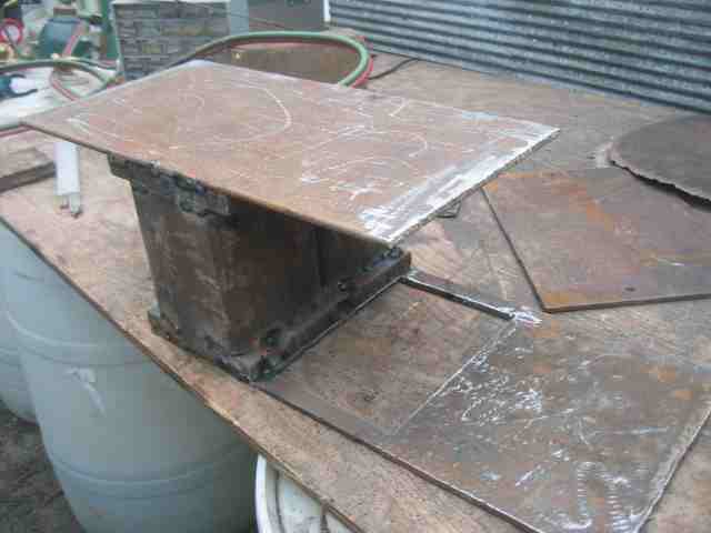
Grind and prepare pressing plate assembly:
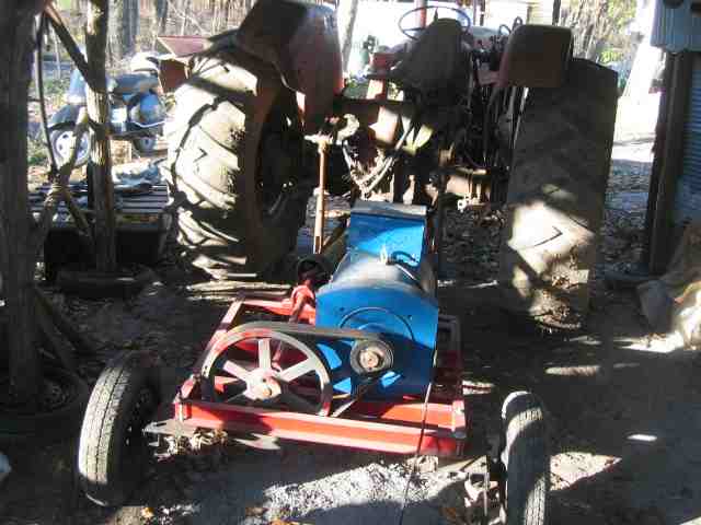
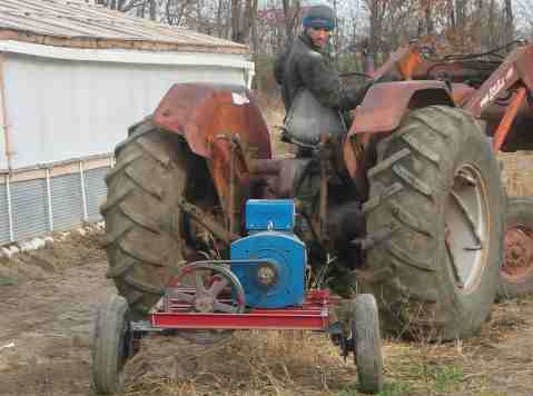
We used a 20 kW tractor power-take-off (PTO) genearator to feed the welder.
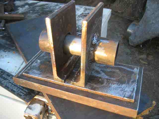
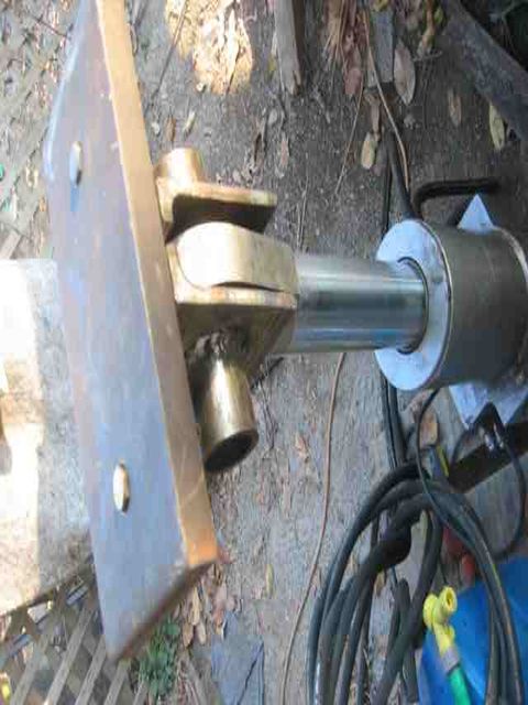
Here is the prepared pressing plate assembly with cylinder pin:
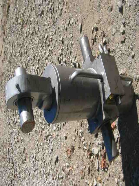
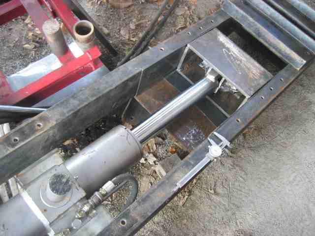
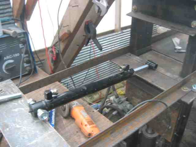
Add the 5 inch, 2.5 inch rod, ~20 ton hydraulic cylinder:
Fit the pressing plate assembly on the cylinder:
Prepare sides of the compression plate, so the compression plate assembly moves straight vertically:
Here is the finished press plate and cylinder mount before assembly:
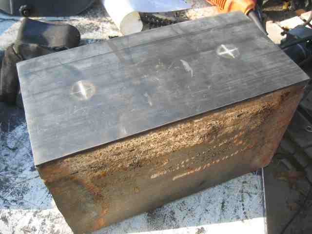
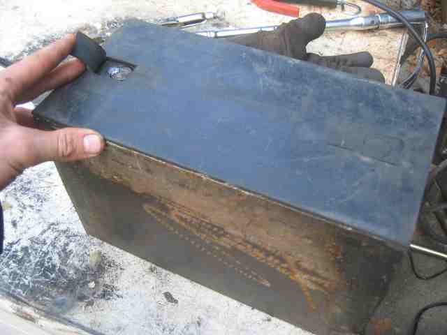
Here is the assembled press plate, with rubber liner on top:
Note how the two pieces are bolted together:
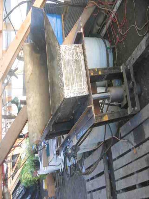
Now we fit the compression box assembly in the frame, attach the cylinder and hydraulics, and test motion of the cylinder:
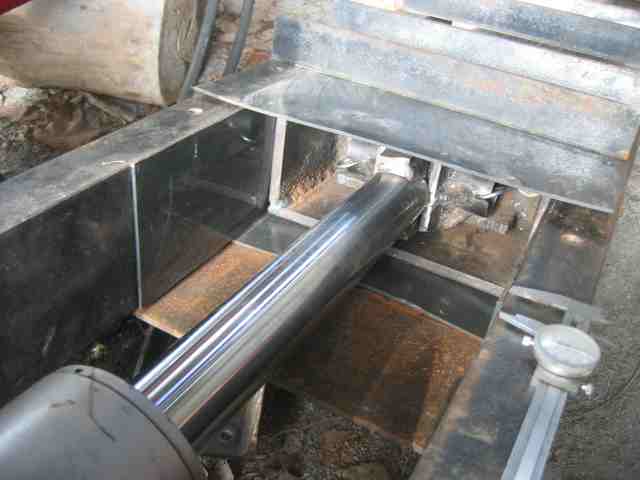
Now we fit the cylinder and press plate into the frame:
We close up the compression box:
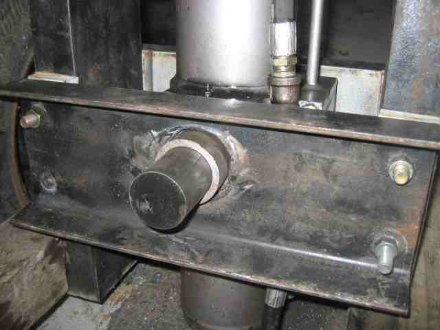
Here we show other details of mounting the cylinder in the frame:
Thy cylinder is mounted and the pin holder is ready for welding:
Winter came, so we moved operations into the greenhouse:
We attached the hopper table to the frame:
And we are ready to test the pressing of the first brick:
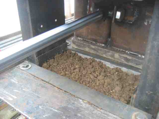
We filled the compression chamber with soil:
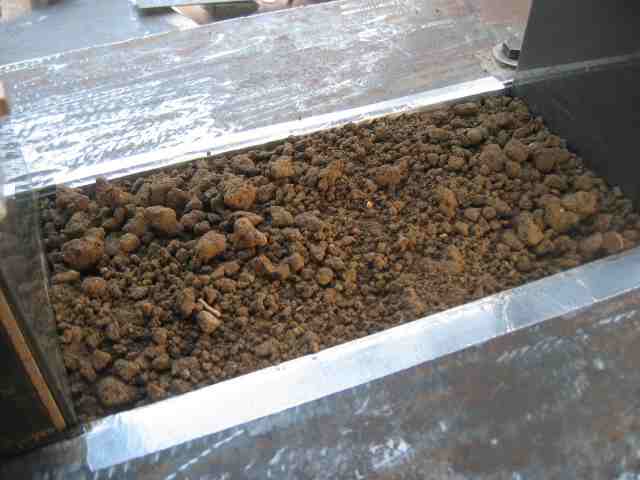 We covered the latch, and fixed it in place (not shown):
And we pressed the first brick:
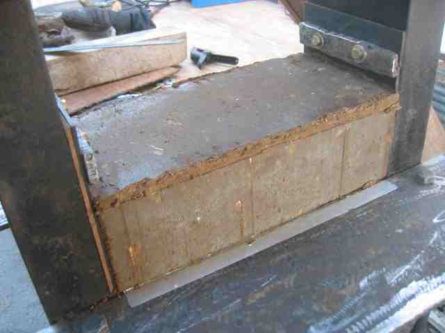
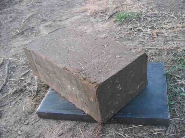
Here is the first block ejected:
We show the block and the earth it's made from:
Next comes the hopper assembly. Here is the hopper cylinder:
Here is the liner for the hopper table:
Here is the hopper assembly in the making. Soil enters the compression chamber through the hole in the bottom plate:
And here is the finished hopper assembly, ready for testing:
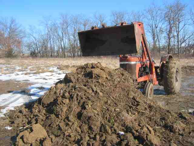
We gather a pile of semi-frozen dirt:
And pack the compression chamber, first manually:
Then we fill the hopper. The soil was too wet, but here are some sample bricks:
And that's it for Phase 1. Now we'll be testing the machine and building an improved prototype with an XYZ torch table to facilitate metal preparation.
