Lucas's Log
Lucas's Log, Summer Internship 2013
June 3
June 4
Work on the MicroTrac:
I'm currently working on this (8:00pm June 4) I will soon have a written description of the day's proceedings and thought processes. For now, here is my work on the MicroTrac:
File:MicroTrac seat and controls (prototype).skp
June 5
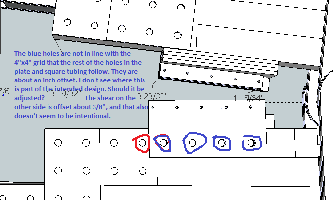
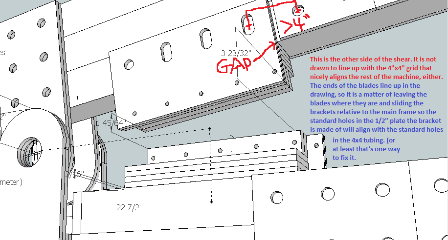
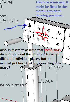
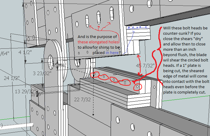
Proof-Reading the IronWorker Drawing
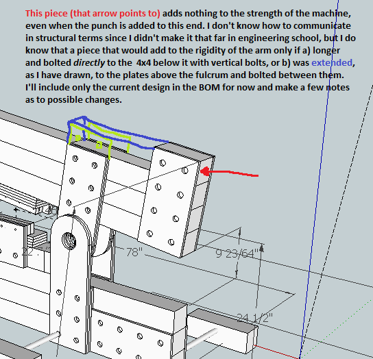
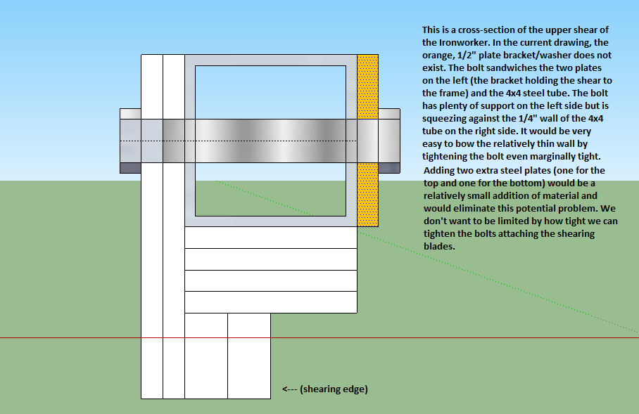
Here is the IronWorker SketchUp file. Design concerns detailed in the images below are not reflected in the updated SketchUp file. This file does have the updated/corrected BOM.
June 6
Hydraulics for the MicroTrac
I am tasked with reading up on basic hydraulic systems and beginning to design the hydraulic pathways that power the components of the MicroTrac (the wheels and the quick attach for the implements). Some of the basics I already know: how hydraulic pistons, pumps, and motors work in conjunction with the fluid reservoir and return tank. I also know that the fluid is being pumped at all times in a short, circular pathway and that valves are used to divert portions of that flow to the various hydraulic components on the machine. I also know that the system will work most efficiently when the hydraulic tubes are directed along pathways that allow for the gentlest curves and bends as practical. That's because the pattern of flow of a fluid within a tube or hose is laminar (friction between the fluid and the inner surface of the tube causes that fluid to move slower and the fluid in the center of the tube moves more quickly). That friction cannot be helped except by increasing the diameter of the hoses or changing the texture of the interior surface of the hoses, both of which are probably optimized by the hose manufacturers. What we must consider in the design is the routing of the hoses for best performance. When there are obstructions in the hose or sharp bends, turbulence increases friction dramatically and can sometimes bring the fluid nearly to a stop. When designing a micro-hydro power system at home, I had to learn about all these things about fluid flow. More updates and drawings to follow...
New things I've learned:
- The exit ports coming off of the valve control panel should face their destination. That way, straight fittings can be used, as opposed to elbows which were used exclusively on the first LifeTrac and used less on the most recent version. A combination of smooth, gently-curved pathways and short pathways help reduce drag. Also, apparently, cavitation is an associated problem with turbulence in hydraulic systems. I thought it was only a problem with water.
- straight fittings reduce the number of potential leak points as compared with using elbows. Low maintenance and durability are priorities of OSE machines.
- The hydraulic system used by OSE is an open system. (Apparently there exists a closed system used on many tractors where the fluid only flows when a valve is opened and a demand is placed on the system.)
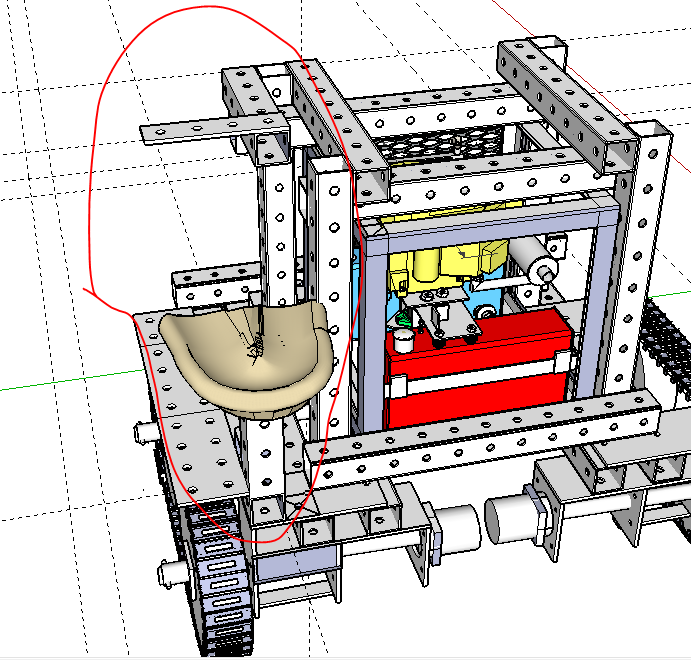
Before I could start drawing and designing the hydraulic setup, I had to design the seat and control panel in SketchUp. This was very frustrating adding to the current model of the MicroTrac because almost nothing on the frame lines up with the 4x4 grid the holes are spaced for. Almost nothing I added to the frame lined up. I attempted to try to re-align the components of the frame, but there are so many things already built onto the frame, that I couldn't move one thing without messing up another piece. Maybe this is not important because it is a prototype model, but if we're going to the trouble to line other things up and make the model work, it seems the main frame we're building off of should be a drawing that is workable.
Also, the hydraulic switches/valves an all 3 versions of the LifeTrac are bolted to 4" by 1/4" steel plate, which isn't in the warehouse. I used 1/2" plate instead which seems like overkill, but like everybody on the team, I'm getting used to the limitations (or advantages, depending on your perspective) we have by using the warehouse.
The above image is of the seat and seat mount, the control mount, and the "splash" guard added to protect the operator from the tracks.
June 7
Hydraulics for MicroTrac (continued)
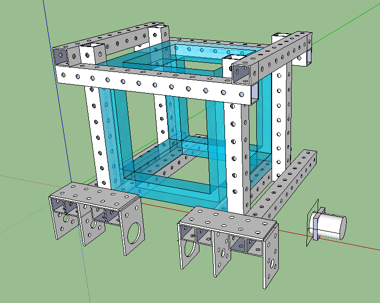
Unfortunately, in the warehouse file we started out using, the 4x4 steel tubes were made of four 4"x1/4" plates, and so had multiple intersection points. This made it very easy to mis-align the tubes, and that's apparently what happened in the original MicroTrac frame. As a result, almost none of the holes lined up, and everything was out of line with the standard 4x4 grid everything is supposed to be on. I rebuilt the frame (at the moment still working on it) with some improvements. One improvement is that the square opening in the top of the frame is now big enough for the PowerCube to be hoisted out. This was a major design aspect (because of frequent maintenance requirements), and we discussed this on our first or second day on site. I'll have some screenshots up shortly and an updated SketchUp file by the end of the day.
Also, the PowerCubes in the shop are almost all of different dimensions. I'm sure this is on the list of things to standardize, especially with the recent push to move toward using components from the warehouse as much as possible. As it is, though, none of the dimensions of any of the PowerCubes are multiples of 4" and range from 27" to 30 inches. to insure that current (and presumably future) PowerCubes fit, I'm building the frame to allow for a 32" cube (8 four-inch units)
Since the PowerCube file is so large and slows things down on a SketchUp page I created a 32" cube to simulate the PowerCube. It can take the place of the PowerCube until the model is at a point where the actual model pf the PowerCube is needed or wanted. I added this cube to the Warehouse file.
Another great tool I discovered is a plugin for Sketchup called 3Skeng. It is specifically designed for creating tubing and duct work in SketchUp models and supposedly has a feature that routes tubing via pathways that do not interfere with existing components in a model. For example, it won't let you accidentally have a PVC pipe running through a steel beam unless you intentionally tell it to. I've been learning its features. http://www.3skeng.com/en/index.htm
File:Microtrac preliminary.skp
The .skp file above doesn't yet have many of the finished components added to the drawing. Those will be added when the frame is more complete. Many of the components on the old frame (the axle brackets, for example) were not even made from warehouse components. This new version has/will have many more appropriate components made from standard components.
