Lucas's Log
Sat & Sun Sep 14-15, 2013
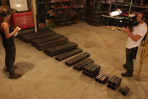
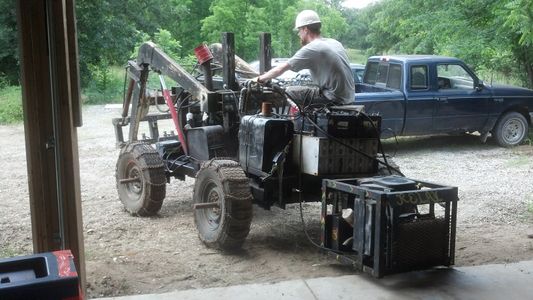
Cleaned the shop in preparation for cutting and LifeTrac 6 work. Started cutting of 4x4 tubing and plates for LifeTrac 6. I also began welding the DOM rings inside the pivot plates. I had to make a new jig for the smaller DOM size, and the 1/2" rings are being made currently out of the smaller DOM tubing. All 4x4's are cut and arranged by length. They will be arranged by module when I get a list laid out by module. Gary has been doing work instructions, so I've been in charge of the shop. Besides myself, there are between 1 and 3 other people working. They are fairly self-sufficient, but I'm the POC for any and every issue that springs up, so the amount of work I do personally is decreased. Remaining fasteners arriving tomorrow, so when the rest of the cutting is finished, there should be no delay in starting the build. Normal work day Saturday 6 hour day Sunday.
Fri Sep 13, 2013
File:LifeTrac 6 (v9-13-13 2030).skp
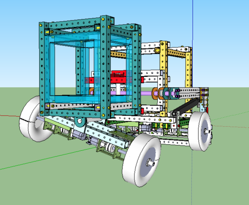
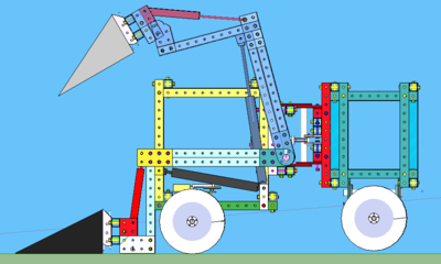
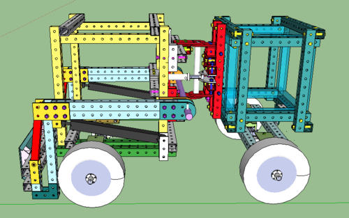
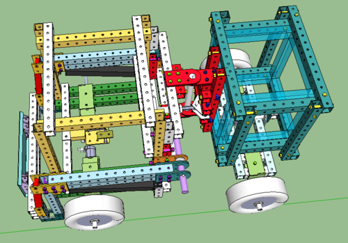
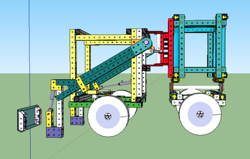
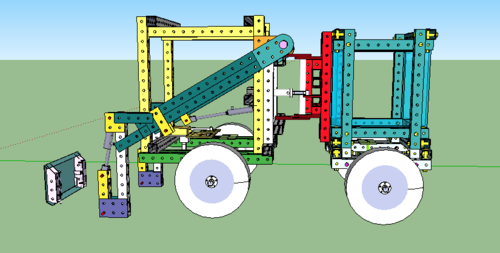
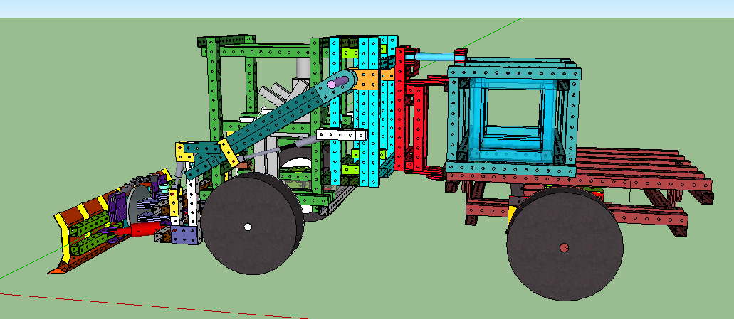
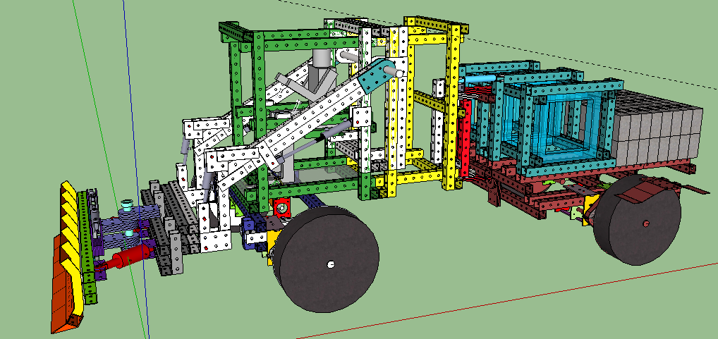
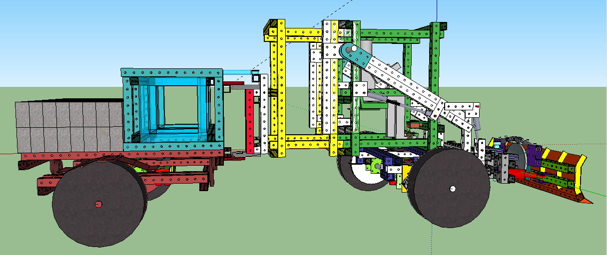
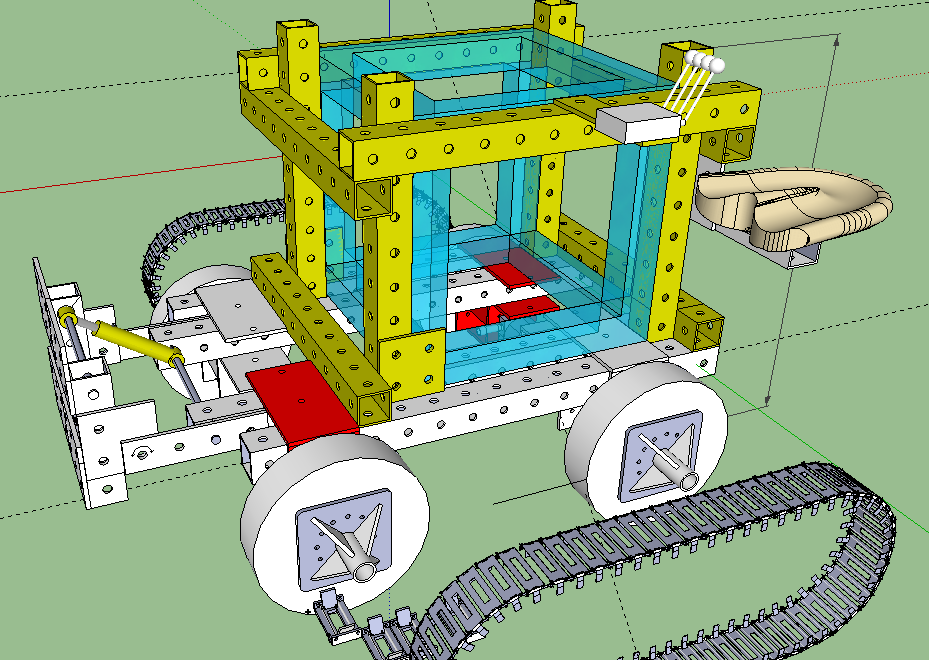
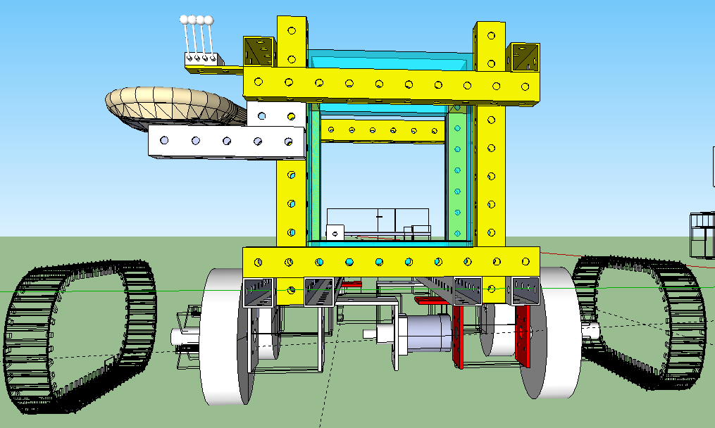
This file of LifeTrac 6 has a functioning steering pivot, includes the actual seat that will be used, has the most acurate cylinders that will be used (all previous versions of this file had a 32" cylinder for the loader arms that was drawn 1.5" too long). It also reduces the length of the articulation joint shaft by 6" and eliminates the need for DOM spacers in that pivot joint. I also propose that the long beams that span the distance between the wheels be tubing that has not had holes cut in it. These pieces will be welded anyway, and if anything needs to be bolted to the rear of the tractor, such as a three-point hitch, it will be attached to the main frame, not the rocking portion where the wheels are.
Mon Sep 9, 2013
Starting work instructions, ordering the fasteners, unloading our steel order from Cloverdale, driving to St. Jo to pick up the card and on to Kansas City to pick up the fasteners from Grainger and Mo-Kan and to pick up Gary at the airport. The cylinder mounting for the steering pivot joint has to be completely changed. The pin eyes are oriented horizontally, in the same plane that the pivoting happens.
Sun Sep 8, 2013
Lots of grounds work at FeF.
Sat Sep 7, 2013
Helped James with CEB 2. 6 hours of fixing other people's mistakes.
Fri Sep 6, 2013
Finished up tracking down sources for all remaining parts and materials needed for LifeTrac6, except tires. We can use the old tires taken off LifeTrac 3 to replace LifeTrac 3's tires, but we still need 4 knobbly tires that will fit a 16" rim that's 6.5" wide. The requisition form for parts is here:
As of Monday morning, it is being looked at it.
Wed Sep 4, 2013
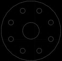
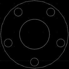
The following file is to be added to the Cloverdale laser cutting order. There are 8 holes that are 3.25" from the center of the hub and 3/4" in diameter to accommodate a 5/8" lug bolts. The center hole is 2 1/2" in diameter for the 1 3/8" sleeve tubing used in the hub assembly.
File:Wheel hub mounting plate for LifeTrac 6 wheels (8x6.5 bolt pattern ,75in holes).dxf
Fri Aug 30, 2013
Here is a spreadsheet of the parts needed for the LifeTrac 6 build. I think there should be a quick ROM check to make sure that the cylinders we are ordering do, in fact, do what we hope they will given the current geometry.
Thu Aug 29, 2013
Assessed the parts still needed to build 8 quick attach wheel mounts. Laser-cut steel order is in, so not much else needed for the wheel assemblies. I'll have a spreadsheet of all needed parts for LifeTrac 6 tomorrow.
In the evening, we moved the completed CEB press out to the field for testing. I removed the hydraulics from the pulverizer that needs repairing and put them on the other pulverizer. I also simplified the plumbing of the pulverizer. I then mounted a single-spool motoring valve onto the controls manifold of LifeTrac 3.
Mon Aug 12, 2013
File:LifeTrac5 (v9) (reflects most real build changes 8-12-13).skp
Thu Aug 8, 2013
File:Material Awareness Exercise.skp
Wed Aug 7, 2013
Mon Aug 5, 2013
I've been working on updating the SketchUp file we built LifeTrac 5 off of to reflect changes and additions made during the build.
I have also been working on the LifeTrac 5 Prototype Assessment, which includes an analysis of the Design Phase, Build Preparation, Build Phase, Design, Mechanical aspects, Welding and Fasteners, Hydraulics, and Performance Data.
Fri Jul 26 - Fri Aug 2, 2013
Ideal Future State July 2013
- Page 1 of 4
- Page 2 of 4
- Page 3 of 4
- Page 4 of 4
Current State July 2013
- Page 1 of 4
- Page 2 of 4
- Page 3 of 4
- Page 4 of 4
- Current State July 2013 Matrix
Wed Jul 24, 2013
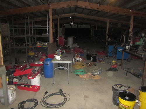
A thorough deep cleaning and organization of the shop this week after the tractor build with The Spark Documentary crew. Also taking inventory or all key supplies. There's a new crop of DPVs here and the third iteration (since I arrived at the beginning of June) of cleaning or the HabLab has been completed.
All smooth wood surfaces (drawer interiors, shelves, etc.) have been given 2 coats of tung oil finish, separated by 12 hour drying time. The particle board interiors of the cabinets have been given a thin coat of spray-on polyurethane to combat moisture and associated problems. Floor was scrubbed with baking soda and vinegar mix. The skylight was cleaned. The fridge was dismantled and scrubbed. All broken and/or redundant kitchen things have been removed. The smelly drain in the kitchen floor has been sealed. Etc, Etc.
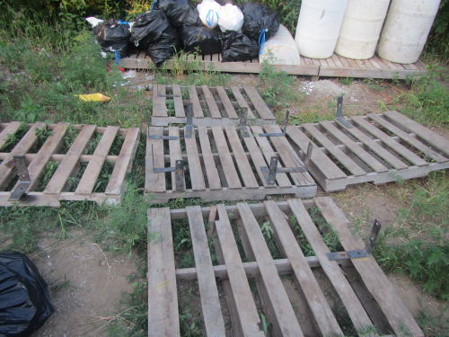
Dave and I built a trash bin. With weekly trash pick-up now, hopefully it will not accumulate again, but there is a place to keep it out of reach or dogs and coons. Something still got in so maybe chicken wire around the outside will be necessary.
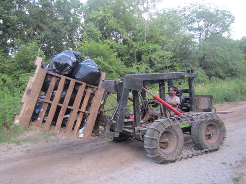
For the record, this was the most fun Miguel has ever had taking out the trash.
This is the current state of the shop. Already this summer, the culture here had transformed. Hopefully, the shop will never reach the state it was in at the beginning of the summer. The same goes for the kitchen. If you want kombucha, you'll have to brew it out in the woods. It will be killed if it enters the kitchen. And never again will anyone save an entire box of stripped plastic off the ends of electrical wiring.
Some things are done. All nuts, washers and bolts from 1/4" to 1" have been sorted, labeled and counted (sometimes approximately) and are ready to be entered into Dave's Google Doc. 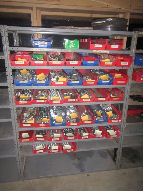
Other completed tasks:
- Drill press fixed
- All bolts from old shop assimilated with new shop inventory
- Guards put on all angle grinders
- Old backhoe moved to storage with other machines.
- Small band saw blade replaced
- Drill bit/machining tools sorted and organized. Indexes have been filled and extras put in labeled drawers.
- Chains and extension cords have been sorted and have found a home
- Safety stuff has been sorted. Unrepairable items discarded.
- Power tools have been sorted Broken/Working
- Dave made a paper towel holder for the kitchen out of scrap
Still to do:
- Finish cleaning and organizing large shop shelves
- Fix guide on teal IronWorker
- Sort and inventory wrenches and sockets
- Build a wheel stand for a PowerCube so it can by wheeled around the shop
- Buy plenty of soap stone.
TRACTOR BUILD (11-18 July 2013)
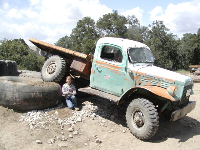
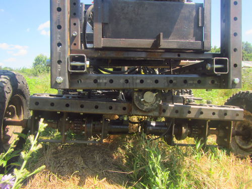
I still have a lot to update in this section, but here is a portion on the ground-hug pivot: The Dodge Powerwagon is where I got this idea.
Fri Jul 12, 2013
The second half of Friday was when we cut all of the material.
This is the finalized model from which the BOM was created:
Assembly instructions - loader arms: https://docs.google.com/presentation/d/17IC0ZGxGzxVMeWpaWA5iOAxb-NreVPff2JHB2xLwV9k/edit?usp=sharing
File:Final Loader Arms (v1).skp The BOM is included in the skp file.
Thu Jul 11, 2013
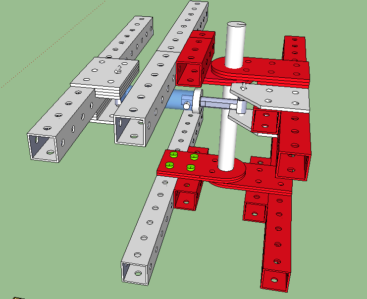
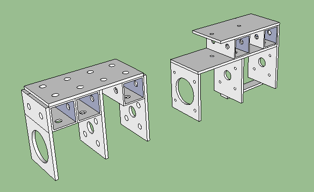
Below is a late-stage design overhaul of the articulated steering pivot.
File:Cab and Loader Arms 12pm Jul 11.skp
Wed Jul 10, 2013
Tue Jul 9 2013
File:LifeTrac4 (v2).skp One change that is not reflected in this version is the added space in the back for the weights. Everything else is up to date as of noon today.
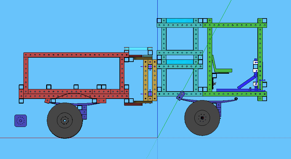
The steering pivot design I came up with allows for 70 degrees of turning (30 or a little more in one way and 40 in the other). This is using the 3x8" cylinder as requested by Marcin. The Cylinder goes in the middle of the pivot (as opposed to above or below it as in earlier designs. There are no physical conflicts of metal-on-metal. In short: great news!
Above is the version with the ground-hug pivot. As it is, it is pretty precarious-looking. I drew up a modified version without the ground-hug pivot but did not polish it up. I don't think the folks in New Orleans will be rolling over boulders. It would be considerably simpler without the ground-hug pivot as pictured below.
In my opinion, it seems like it is one of those things that seemed like a good idea, and as the design progressed, it started turning into not so good of an idea and we just didn't question it because, well, I don't know.
Monday July 8, 2013
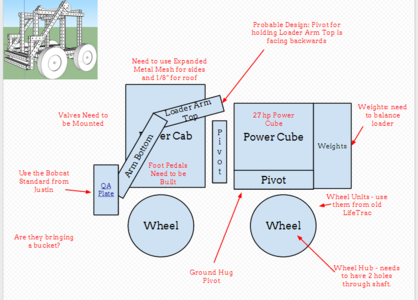
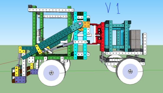
This is the stick drawing we started with on Monday next to version 1 of a few hours later.
Sat Jun 29 2013
File:MicroTrac (v8).skp
Mon Jun 24 2013
Final syncing of dozer and truck. All components that coincide on the truck and dozer line up, match, and work together. These are the final uploads for this prototype.
File:Bulldozer in Progress 630pm 24Jun.skp
File:Truck Full 700pm 24Jun.skp
The file below is now outdated, as are the pictures.
File:Bulldozer in Progress 2pm 24Jun.skp
Sun Jun 23 2013
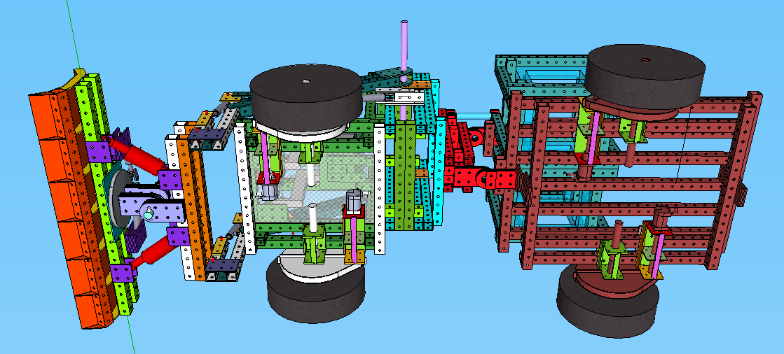
Bunch of work on the Bulldozer. 48x100-pound concrete weights are included and much more. A lot of people's work went into this!
File:Bulldozer in Progress 5pm 23Jun.skp
Sat Jun 22, 2013
This is the Trucktor as of 3:00pm. 3" quick attach wheel mounts in place; leaf spring conflicts resolved; Cab, PowerCube, pivot and bed lined up and centered.
File:Truck Full 062213.skp
Thu Jun 20, 2013
Moving LifeTrac One out of the shop area. For the record, the articulated steering system is much nicer to use than the tracks on the newer LifeTracs
Tue Jun 18, 2013
File:All Three Wheel mounts ready for DXF conversion (v1).skp
File:All Three Wheel mounts ready for DXF conversion (v3) with 6 inch hole spacings for 3 inch bearings.skp
- Part 1 DXF file - File:Wheel Mounts Part 1.dxf
- Part 2 DXF file - File:Wheel Mounts Part 2.dxf
- Part 3 DXF file - File:Wheel Mounts Part 3.dxf - 6" bolt centers - meaning large bearing; not conistent with above screenshot
- Part 4 DXF file - File:Wheel Mounts Part 4.dxf
- Part 5 DXF file - File:Wheel Mounts Part 5.dxf
- Part 6 DXF file - File:Wheel Mounts Part 6.dxf
- Part 7 DXF file - File:Wheel Mounts Part 7.dxf
- Part 8 DXF file - File:Wheel Mounts Part 8.dxf
- Part 9 DXF file - File:Wheel Mounts Part 9.dxf
- Part 10 DXF file - File:Wheel mounts Part 10.dxf
- Part 11 DXF file - File:Wheel Mounts Part 11.dxf
Part Quantities
Wheel mount file Double-checked with Marcin against existing wheel mounts: Some holes moved and a few dimensions modified.
Some more edits have been made (8:10pm) more corrections, color-coded by part type (Now v3)
Notes
- 4.37" bolt pattern for 1-7/8" shaft collars
- Note - there are 2 kinds of 3" bearing hole patterns. The one with the collars is 6" - [1]. The one without collars has a 6.26" hole separation - [2]
Wheel Hub
File:Wheel Hub for MicroTrac.dxf
Mon Jun 17, 2013
Sat Jun 15, 2013
File:PowerCube Module (15 Jun '13).skp
File:MicroTrac (v6).skp
This version of the MicroTrac file contains the finalized wheel mounts. Tracks still need to be added.
File:All Three Wheel mounts ready for DXF conversion (v1).skp
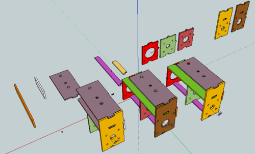
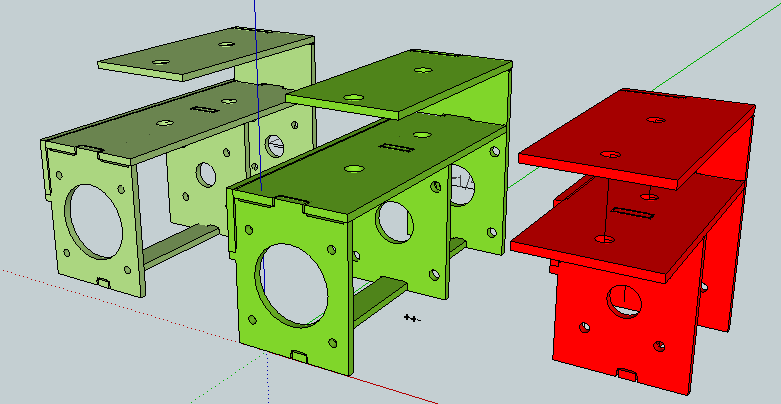
These are the wheel mounts ready to be converted to DXF files. Three different wheel mounts all designed for 1/8" spaces for the welds are in this file.
- 1 7/8" size (shortened for freewheeling)
- 1 7/8" size with holes for motor mount
- 3" heavy duty wheel mounts for bulldozer
Thu Jun 13, 2013
File:Wheelmount Updated 6 12.skp
Wed Jun 12, 2013
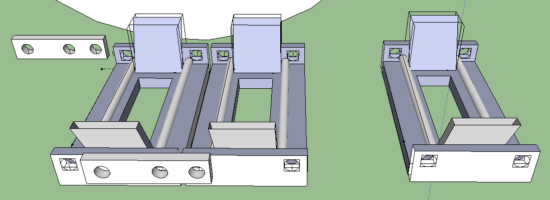
This is a parallel projection view of the quick attach and hydraulic cylinder for the MicroTrac. 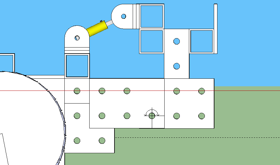
Below is a slimmed down version of the MicroTrac quick attach component, as well as a different cylinder with at 1" pin. The cylinder ought to be kept close to one side or another so the 1" bars don't bend in the middle. The plates in front may be welded or probably bolted together with 8"x4" brackets from the warehouse.
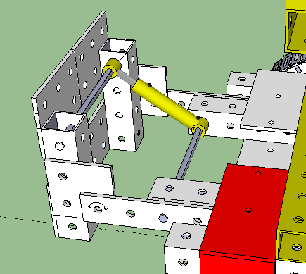
Below is the end of the day's work. Wheels are lined up exactly with the quick attach wheel mounts and out 1" from the sides of the frame. It is 53 inched wide. The tracks were not easily made longer to fit, and these are not the tracks that we are using. Farther below is a larger (fewer pieces) version of the tracks that Cory drew up last week. Marcin also mentioned that we need the tracks to be made of larger/longer pieces so there are fewer pieces to fabricate. There is also no guard drawn yet to protect the operator from the moving tracks.
Below is the track design Gary (I think) discussed with Cory. It needs a few modifications so it moves properly and doesn't bind (It was designed when none of us knew much about SketchUp).
Newest MicroTrack .skp file:
File:MicroTrac (v5).skp
Tue Jun 11, 2013
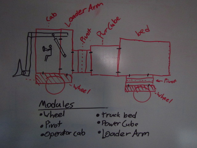
Fantastic group meeting with Marcin and Gary this morning. Finally starting to see the big picture and what we are actually working toward. That helps for general morale and it puts everyone on the same page as far as design trajectory. It also helps me know if the ideas I have are relevant to the goals of the team.
The image above illustrates the one of the over-arching concepts we discussed in the meeting. The idea is that the modules will stack or sandwich together in any practical configuration. This is useful both as a characteristic of a modulat construction set, but also in the manufacturing of the machines. Focused teams can fabricate a particular module and when everyone is done, they can be bolted together using the agreed-upon interface. Currently, the pivot is the narrowest (laterally) of all the modules at 2 feet wide, so the interface at this stage are vertical 4x4 tubes set 2 feet apart. These matching columns are what are bolted together.
I also brought up the idea of using warehouse parts for the quick-attach wheel mount brackets. This would eliminate 32 welds used on the guides, and 24 welds on the custom wheel attach brackets (counting all 4 wheels) and would increase the number of bolts used by about 8. Below is my idea for that. Just a thought for now, but one idea brought up was prototyping one and using it for one of the 4 wheels and seeing how it held up
After the meeting, I set about working out some more things with the new and improved (narrowed) MicroTrac from Gary. I thought I had a plan for lowering the PowerCube so the bottom of it would be no higher than the bottom of the wheel mounts. my idea didn't work, but if we lengthened the distance between the front and rear wheel mounts, then the PowerCube could be lowered down between the chassis. Narrowing it was a big goal, as it turned out, and making it shorter is another priority.
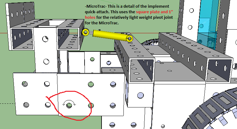
I also fixed a few details Marcin pointed out, including making the pivot for the MicroTrac out of regular plate and using a 1-inch pin for the pivot. He said that's all it needs, and I agree. See the image below
The thing I'll work on at the beginning of tomorrow because I didn't get to it today is to design the actual PowerCube Module that will interface with all the other modules.
Mon Jun 10, 2013
MicroTrac Overhaul
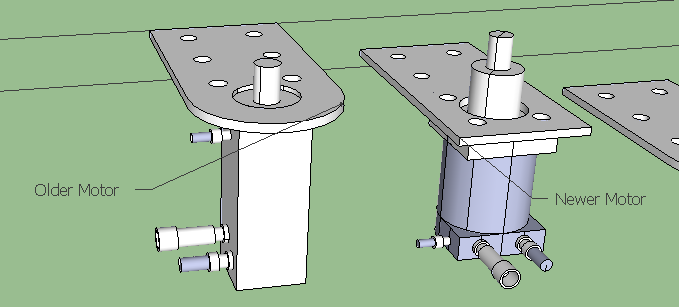
Big design changes today all around. I got some direction on some of the important parameters of the MicroTrac. One of the big unknowns limiting the amount we can design was not knowing the dimensions of the hydraulic motors. I made full-scale models of the 2 main hydraulic motors used on the current completed machines and added them to the warehouse file.
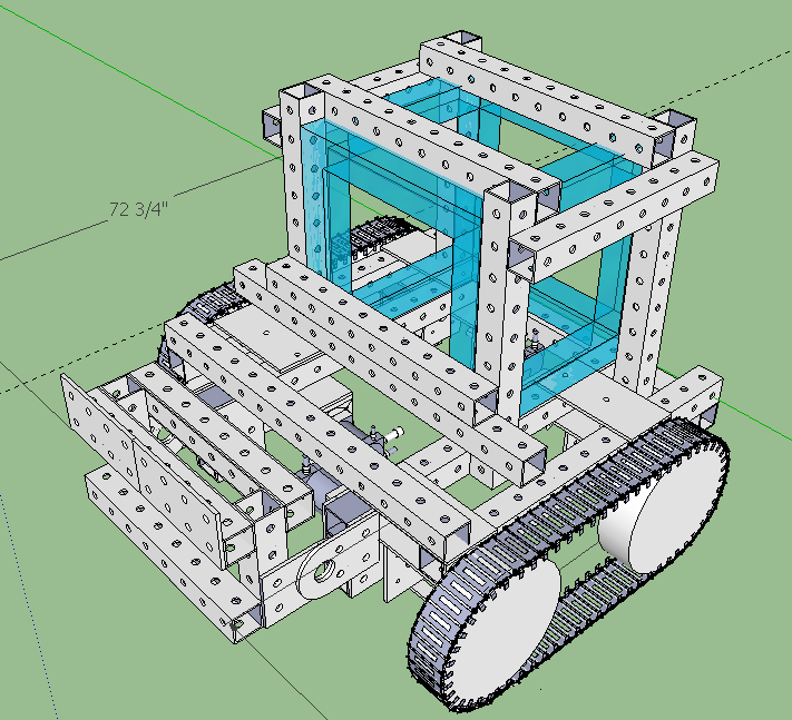
Here is the work I did on the MicroTrac. It must be as narrow as possible. The PowerCube will be inserted from the back.
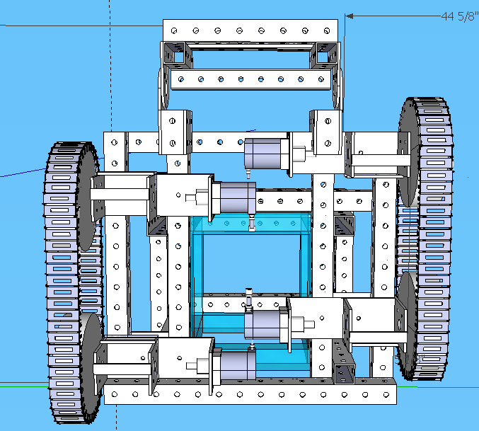
This view shows the offset tracks that allow the tracks to be closer together because the . I didn't get to actually narrowing the frame yet, but you can see the possibilities now that the hydraulic motors nestle beside each other.
I still don't understand the benefit of the current system of mounting the axle brackets. On the LifeTrac, that system requires 32 welds, 8 bolts, and doesn't use warehouse components. The only advantage I see is that there are only 2 bolts per wheel that need to be removed to remove the wheel mounts. It would be much easier to use warehouse components, 4 bolts per wheel and eliminate 32 welds from the construction. One of the stated goals of this design strategy is specifically to use standard components and minimize welds.
Fri Jun 7, 2013
Hydraulics for MicroTrac (continued)
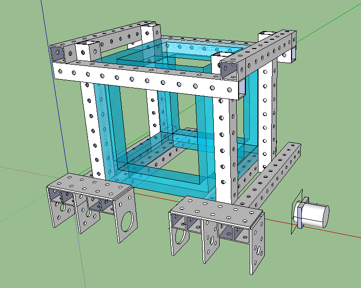
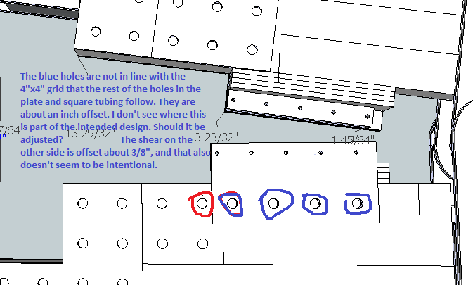
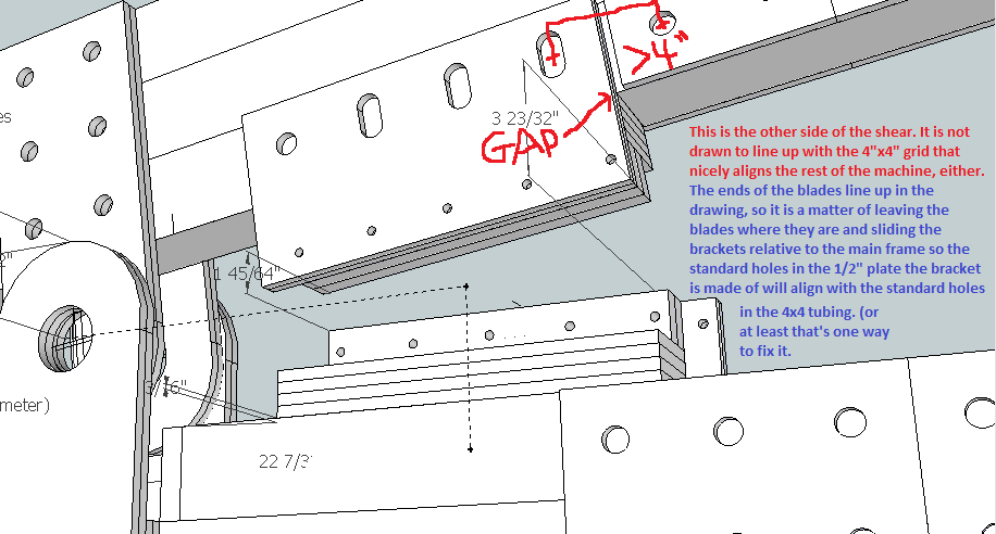
Unfortunately, in the warehouse file we started out using, the 4x4 steel tubes were made of four 4"x1/4" plates, and so had multiple intersection points. This made it very easy to mis-align the tubes, and that's apparently what happened in the original MicroTrac frame. As a result, almost none of the holes lined up, and everything was out of line with the standard 4x4 grid everything is supposed to be on. I rebuilt the frame (at the moment still working on it) with some improvements. One improvement is that the square opening in the top of the frame is now big enough for the PowerCube to be hoisted out. This was a major design aspect (because of frequent maintenance requirements), and we discussed this on our first or second day on site. I'll have some screenshots up shortly and an updated SketchUp file by the end of the day.
Also, the PowerCubes in the shop are almost all of different dimensions. I'm sure this is on the list of things to standardize, especially with the recent push to move toward using components from the warehouse as much as possible. As it is, though, none of the dimensions of any of the PowerCubes are multiples of 4" and range from 27" to 30 inches. to insure that current (and presumably future) PowerCubes fit, I'm building the frame to allow for a 32" cube (8 four-inch units)
Since the PowerCube file is so large and slows things down on a SketchUp page I created a 32" cube to simulate the PowerCube. It can take the place of the PowerCube until the model is at a point where the actual model pf the PowerCube is needed or wanted. I added this cube to the Warehouse file.
Another great tool I discovered is a plugin for Sketchup called 3Skeng. It is specifically designed for creating tubing and duct work in SketchUp models and supposedly has a feature that routes tubing via pathways that do not interfere with existing components in a model. For example, it won't let you accidentally have a PVC pipe running through a steel beam unless you intentionally tell it to. I've been learning its features. http://www.3skeng.com/en/index.htm
File:Microtrac preliminary.skp
The .skp file above doesn't yet have many of the finished components added to the drawing. Those will be added when the frame is more complete. Many of the components on the old frame (the axle brackets, for example) were not even made from warehouse components. This new version has/will have many more appropriate components made from standard components.
Thu Jun 6, 2013
Hydraulics for the MicroTrac
I am tasked with reading up on basic hydraulic systems and beginning to design the hydraulic pathways that power the components of the MicroTrac (the wheels and the quick attach for the implements). Some of the basics I already know: how hydraulic pistons, pumps, and motors work in conjunction with the fluid reservoir and return tank. I also know that the fluid is being pumped at all times in a short, circular pathway and that valves are used to divert portions of that flow to the various hydraulic components on the machine. I also know that the system will work most efficiently when the hydraulic tubes are directed along pathways that allow for the gentlest curves and bends as practical. That's because the pattern of flow of a fluid within a tube or hose is laminar (friction between the fluid and the inner surface of the tube causes that fluid to move slower and the fluid in the center of the tube moves more quickly). That friction cannot be helped except by increasing the diameter of the hoses or changing the texture of the interior surface of the hoses, both of which are probably optimized by the hose manufacturers. What we must consider in the design is the routing of the hoses for best performance. When there are obstructions in the hose or sharp bends, turbulence increases friction dramatically and can sometimes bring the fluid nearly to a stop. When designing a micro-hydro power system at home, I had to learn about all these things about fluid flow. More updates and drawings to follow...
New things I've learned:
- The exit ports coming off of the valve control panel should face their destination. That way, straight fittings can be used, as opposed to elbows which were used exclusively on the first LifeTrac and used less on the most recent version. A combination of smooth, gently-curved pathways and short pathways help reduce drag. Also, apparently, cavitation is an associated problem with turbulence in hydraulic systems. I thought it was only a problem with water.
- straight fittings reduce the number of potential leak points as compared with using elbows. Low maintenance and durability are priorities of OSE machines.
- The hydraulic system used by OSE is an open system. (Apparently there exists a closed system used on many tractors where the fluid only flows when a valve is opened and a demand is placed on the system.)
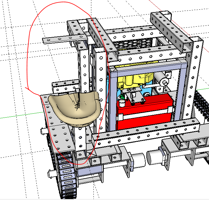
Before I could start drawing and designing the hydraulic setup, I had to design the seat and control panel in SketchUp. This was very frustrating adding to the current model of the MicroTrac because almost nothing on the frame lines up with the 4x4 grid the holes are spaced for. Almost nothing I added to the frame lined up. I attempted to try to re-align the components of the frame, but there are so many things already built onto the frame, that I couldn't move one thing without messing up another piece. Maybe this is not important because it is a prototype model, but if we're going to the trouble to line other things up and make the model work, it seems the main frame we're building off of should be a drawing that is workable.
Also, the hydraulic switches/valves an all 3 versions of the LifeTrac are bolted to 4" by 1/4" steel plate, which isn't in the warehouse. I used 1/2" plate instead which seems like overkill, but like everybody on the team, I'm getting used to the limitations (or advantages, depending on your perspective) we have by using the warehouse.
The above image is of the seat and seat mount, the control mount, and the "splash" guard added to protect the operator from the tracks.
Wed Jun 5, 2013
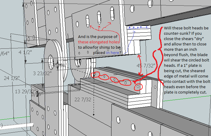
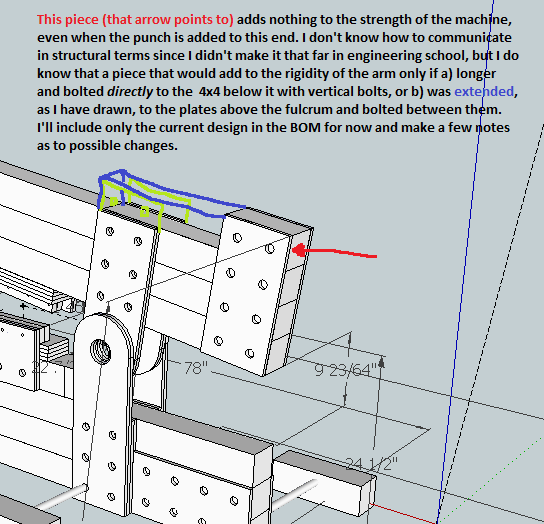
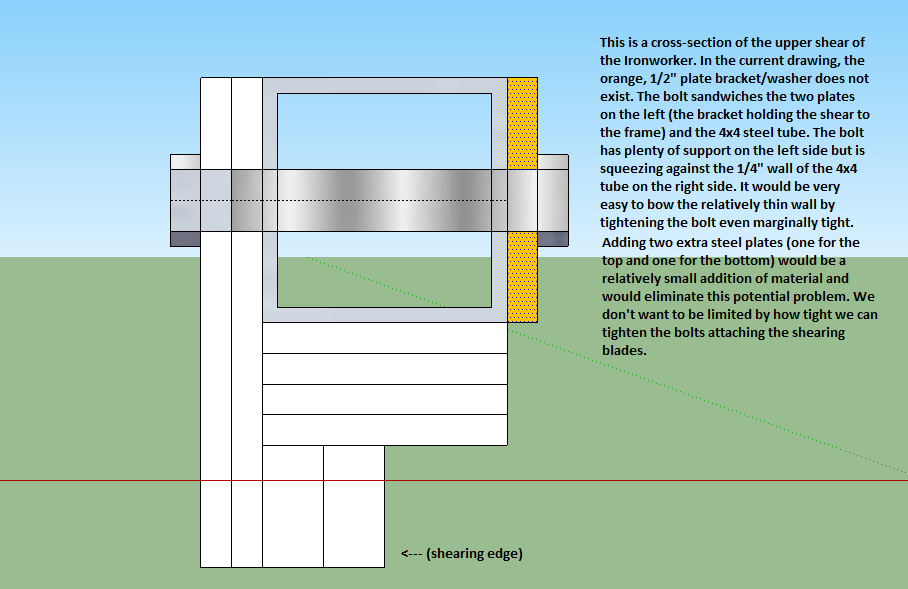
Proof-Reading the IronWorker Drawing
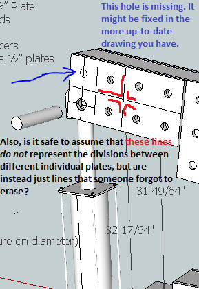
Here is the IronWorker SketchUp file. Design concerns detailed in the images below are not reflected in the updated SketchUp file. This file does have the updated/corrected BOM.
Tue Jun 4, 2013
Work on the MicroTrac:
I'm currently working on this (8:00pm June 4) I will soon have a written description of the day's proceedings and thought processes. For now, here is my work on the MicroTrac:
File:MicroTrac seat and controls (prototype).skp
A lot of questions came up today, including some things about the purpose of the MicroTrac. It seems the biggest factor limiting how small the MicroTrac can be is the size of the PowerCube. In addition, we were told that the 4"x4" steel tubing frame surrounding the existing angle iron frame housing the PowerCube is something that must be a part of the prototype design. My task today was to figure out where and how the seat and controls are going to be mounted. I imported (from the 3D Warehouse of SketchUp) and modified a tractor seat and a control panel of hydraulic switches. Gary has been super helpful and available over Skype, but with Marcin at the White House and Audrey busy taking care of people arriving and leaving, there was some lingering confusion throughout the day. For example, it was hard to tell which way was right-side-up on the PowerCube that my co-designers were working on, and we still don't know which is the intended front end of the frame. Concerns I have:
- Because this machine relies on gravity alone to keep it upright, as opposed to a walk-behind garden tractor that is kept upright with some help from the person walking behind it, I am concerned with the top-heaviness along with the short wheelbase and the lateral narrowness. Even on flat ground, as the design stands now, a quick squeeze of the throttle and the machine could probably pop a wheelie.
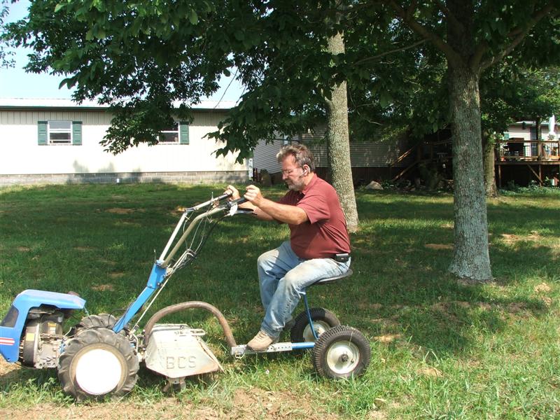
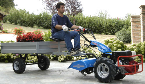
- Another concern I have is the weight of the MicroTrac. In large cultivated fields, one sees the path taken by the large tractor used to do the planting, and nothing grows there (I’m not talking about between the rows). In a smaller garden or cultivated field you can’t afford to be as careless. I think the MicroTrac will do too much compacting of the earth, but I am not a farmer and I don’t know. However, I do look at similar machines made by commercial manufacturers and sometimes modified by farmers, such as the BCS walk-behind tractor, and what I see is a bare-bones design, an easily maneuvered, multi-implement garden/small farm machine that is relatively light-weight. Make one out of modular parts and it seems we have a machine we already know people love using. It seems to me we are designing an extremely awkward miniature tractor with the added complications of metal treads in place of the time-proven wheels found on all other micro-tractors. Farmers have made modifications to these commercial designs to convert them to ride-behind machines. These modifications are bare-bones, as well. See attached pictures.
As far as I can tell, the purpose of the MicroTrac is to be a multi-implement machine capable of doing many of the same tasks as a tractor within the confines of smaller physical spaces. This premise shaped the brainstorming discussions we had.
The MicroTrac could also be used as transportation for the Powercube. Because the Powercube is used as the central power unit of so many machines in the Global Village Construction Set and weighs several hundred pounds, making it mobile is a must.
