2" Universal Axis
![]() Hint: Open Dropbox Link for Master CAD Directory
Hint: Open Dropbox Link for Master CAD Directory
Install A2+ Workbench to edit Assembly, Sub Assemblies, and Parts
More pictures from STEAM Camp 2019 -
Working Doc
CAD - Part Library
Assemblies
Note: These assemblies are formed using workbench A2+. Find this in the FreeCAD addons manager.
Dropbox Link (larger than 1mb)
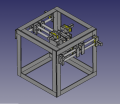
Master Assembly File. Unzip and open D3D Mill Assembly File
TODO: Compression Springs for Z Axis , X Axis Slip Mount Blocks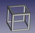
File:Space Frame 2in Universal.fcstd Note: This file bogs down my PC on 0.17 but works good on 0.18.


Individual Parts
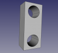
2" Universal Axis Motor Piece - size:nullkb - FreeCAD -File:2axismotorpiece.fcstd. STL - File:2universalaxis.stl
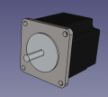
File:23HS45-4204S.FCStd Nema 23 motor. Note this history as well: File:Nema23motor.fcstd
![File:Tb6600.fcstd Toshiba 6600 stepper driver. Source: [1]File:OSE 2inch Universal Axis Motor mount 01.FCStd1](/images/thumb/0/05/Tb6600.png/120px-Tb6600.png)
File:Tb6600.fcstd Toshiba 6600 stepper driver. Source: [1]File:OSE 2inch Universal Axis Motor mount 01.FCStd1
File:2in Half Carriage.FCStd Half Carriage


![File:Tb6600.fcstd Toshiba 6600 stepper driver. Source: [1]File:OSE 2inch Universal Axis Motor mount 01.FCStd1](/wiki/File:Tb6600.png)


Calculations
- Print Time and materials -

- 720 grams for 4x the size of motor piece. One set is 1.44kg, or $30 in materials if using commercial filament.
- Print time 12 hours with 0.8 mm nozzle, 36 hours with 0.4 mm nozzle. Impractical for 0.4 mm nozzle
- Using 0.8 mm nozzle - 24 hours per set, 72 hours per axis.
- May be optimized to $20 materials per set. For 6 axis system, that is 6 pieces per axis - or 36 pieces - or 18 sets. $360 in materials.
- Practical printing really requires our own filament on grounds of cost.
- 2kg for each half at 80% - 4 kg for set - $80 materials per single clam set.
Introduction
Goal is to make belt-driven heavy duty CNC to fit with the Universal Axis concept which is intended to be used for small and large machines at OSE. This will be challenging, so another version with lead screw or ball screw will have to be used if extra strength is required. However, it is useful to do a systematic study of precision based on the number of belts used - and based on using wide, 3D printed belts. Stretch per force applied will be the critical data that will determine the potential accuracy in large force (1000 lb and up) applications. Precision grinding - which requires less force - is still expected to be feasible using simple 3D printed belt systems.
Calculations
Print Time
Look at work doc.
More
- Lead accuracy - motion accuracy per foot - [2] (bad link). 0.004" per foot for regular, 0.001" for precision, and .0005" for precision ground.
- Here is 0.003" per foot accuracy bar - [3]
- 3/4" is 0.009" per foot accuracy. Only $4/foot - [4]
- 1/2", 5:1 acme - 0.009" per foot lead accuracy - [5]
- Ultra precision lead screw - 0.0006" per inch accuracy. This is much worse than above.
- Centralizing acme thread - is called precision acme - it has less radial play. [6]. Classes are 2C, 3C, 4C.
Force
- Using the Universal Axis, but with 2" shafts, allows rod deflection precision of 1/2 thousandth of an inch for a 2 foot by 2 foot working bed. By quadrupling dual belts, only 6 mm wide for low cost - a lateral cutting force of 100-200 lb is sought for heavy duty machinine
- Ball screws are 5000 lb for 16 mm ball screw static force, 2300 lb dynamic force
Ball/Lead Screws + Nuts
- Ball screws are good for 1 thousandth accuracy over 1 foot of distance according to Wikipedia [7]
- Super high precision is obtained by using Invar. It costs $30/foot for 3/8" shafts.
- Lead screws can be used with balls or non-ball nuts - [8] - 3/10 thou per inch runout
Notes
- Acme nuts can be anti-backlash - 2 halves separated by a spring.
- Comparison of ball to lead screw - [11]
- Comparison of ball to lead to acme -
- Cost of acme screw is slightly higher than ball screw -[12]. Is this in general, or just for this specific company?
- Terminology - it appears that acme screws are used interchangeably with lead screws - which have no balls, whereas ball screws have balls
- There is a patent for a lead screw where the lead screw nut compensates automatically for wear to keep the desired stiffness. See ActiveCAM - [13]
- OpenSCAD library for acme threads - [14] - plus other library parts - [15]
Notes
Using the Universal CNC Axis - http://opensourceecology.org/wiki/Universal_CNC_Axis - but enlarged so it's using 2" steel rods, and metal plate is also used to clamp the 3D printed parts together- we would like to do heavy duty CNC.
So that means about 200 lbs of lateral force on the tool head. Can we get to 200 lbs of lateral force with a belt drive, with 1/2 thousandth of belt stretch over a 2 foot working bed? That's how much deflection the 2" rods would have for a 2x2 foot working bed of a CNC machine.
Fig 7 here shows 3.35 in-lb per mm of belt width for GT5 belt, at high speed. We need low speed - GT5 has tooth jump torque of 300 in-lb. So it looks promising for heavy duty CNC. However, Fig 10 seems to be the critical one - showing that only GT2 belts give sub-thousandth positioning accuracy. Figure 8 shows max tooth jump torque for a 5 mm wide belt to be 9 in-lb for a small pulley (20 teeth). Extrapolated linearly to a larger pulley, say 40 teeth, or 1" diameter - that would be 18 in-lb. And further extrapolating to 12 mm wide belt - 43 lb. These are common belts. So if we have 5x gear reduction - we get our 200lb tool head torque. But - would a GT2 belt hold this much torque without breaking? I can't find any data on stretch or force limit of GT2 belts. Sounds like we should be able to get about 100 lb from a 1" width of GT2 belt. So doubling up the axis gets us to 200 lb - it should be doable. Thoughts?
Take tooth jump torque of GT2 at 9 in-lb per 5mm wide belt. Thus, 1" of GT2 is 45 lb. Dual axis is 90 lb total. Assume that tooth jump torque is within working limit of belt, and belt can go higher. So at minimum we have 90 lb of tool torque guaranteed even with GT2 belts. We can multiply belts as needed, given the OSE D3D Belt tensioner which is very simple. So GT2 belt-driven heavy duty CNC is possible from first principles.
Cost - 2" shaft is $15/foot. Each axis costs $60 in steel, $40 in bearings, $10 in belt, and $16 in stepers. Rest is 3D printed. As such we have axis cost of about $150 for a minimum of 90 lb cutting torque machines. The limit of the GT2 belts would be their max working capacity.
Frame: We assembled and tack-welded the 44" cube frame from 6 square sides, each composed of four sections of 4" by 40" plate steel of 1/2" thickness. The sections were cut off from a few very long 4" wide strips using a hydrolic ironworker.
Our technique with the ironworker resulted in the 40" by 4" frame sections having non-squared and not-quite-to-length ends, meaning that the square sides of the assembled frame were extremely difficult to build to within acceptable tolerances. We were not quite successful.
There needs to be a jig that enables the four-section square side assemblies to be quickly and easily laid out in an acceptably perfect position before being welded together.
Each side, when fully assembled, weighs about 91 lbs. We need to develop a method that is both safe and efficient for assembling the sides into the full cube.
Sourcing
GT2 Belts
- See GT2 Belts
Rod
- 2" A36 steel (lower quality than Cold Rolled Steel) - $13/foot for 10' section - [16]
- 2" 1018 Cold Rolled - $17/ft- [17]
- 0.003" per foot accuracy - Rolled Threads Unlimited - [18]
Screw
- 1" centralizing acme - $16/foot - [19]
BOM
As Used
- Coupler - 10 to 8 mm - [20]
- Stepper motor - [21] ( Data Sheet - [22] )
- Stepper driver - [23]
- 8 mm bearings - [24]
- Belt - [25]
- Pulley - [26]
Generic
- Axes - 32' total (8 rods of 3', 4 rods of 2' for z) - $640
- Frame -
1/2"x6"x6" angle -$20/ft; 4x4x1/2 tube - $30/ft - 36 ' - $720 or $1080. Use flts to make 6-sided space frame per OSE industry standards - Oil-impregnated 2" bushing - 8000 lb+ lateral force capacity- $9.41 - [27]. $240. 24 needed, 18 minimum. 2" is huge and weighs about 1 lb each if naval bronze acc to Metal Weight Calculator.

- Belts - see GT2_Belts#Belt_Drive_Cost - $12/foot x6 = under $100.
- Motors - 6 Geared Down Stepper Motors at $30 each -
Precision Drive
- 3D printed belt for low cost precision - needs development
- Multiple 15 mm GT2 Belts
- $25/meter for ball screw only -
- 1" ball screw set - $200/2 meter with complete set - [28]
- $25/foot
- .6" ball screw complete set, 2 foot travel - $50/foot
- $5/foot for 1" acme screw - [29]
Steel + Welding Wire
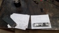
July 2019 Fabrication
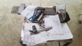
Steel Backing Plate Drawings
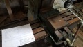
Plate in mill without stop installed
DRO only worked for Y axis
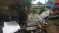
Stop installed on mill table to enable quick swapping of parts

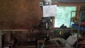
Ganesh
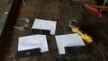
Three types of backing plate
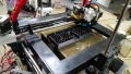
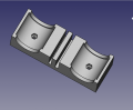
Printing a clamshell

Finished Print

More backing plates
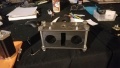
Assembled clamshell
The hydraulic motor on the table would have been the milling head.


Useful Links
- This one says only 25 lb working tension of GT2 belt per inch. But, breaking strength is almost 700 lb per inch, so working tension << breaking strength. To press the limits, operating at 1/10 the breaking strength appears adequat as a 10x safety factor. This means 68 lb per inch of belt - [30]
- Big Gates manual - [31]
Links
- 3" Universal Axis
- 1" Universal Axis
- 5/16" Universal Axis
- D3D 3 Axis CNC Mill
- D3D CNC Torch Table v19.06
- D3D_v19.06_Mega
- NEMA 23 Stepper Motor Data Sheet [32]