Aquaponics IoT
Communications with Aquaponics Lab Team
Gareth, Paulo, Hamish. Newest on top.
Gareth
See Aquaponics Lab IoT Interface BOM]
Hamish
another salient point is that a good ESP board is $10 from Adafruit: http://www.adafruit.com/product/2471
we're runnign a web server on this board, and ok it isn't going to run enterprise java any time soon (or even apache for that matter) but it does do everything a sensor board needs to with the added convenience of wifi + http
like I said in my previous mail though, our current stuff is not yet at product or customer ship stage (don't kill me Gareth!)
h
Gareth
Hello there
Parts are all very widely found, apart from pH interface. It is open source hardware and available from Sparky's Widgets - I just checked and it says they are on backorder!! I could post you one I have spare to get you started - plus I've exchanged emails with him (Ryan) in the past and he's a super nice and helpful guy, I'm sure if you could talk to him you could get something worked out. Last resort is to use his board files to get your own boards made somewhere like oshpark?
I'll put together a BOM over the next few hours.
Our code seems stable, although it is under active development, the two main software authors are both pretty experienced in C and JS respectively. I ran it for 36 hours and didn't see any horrible memory leaks.
Display interface is currently a couchdb visualisation - we'll be plugging it into something like freeboard for a dashboard. The data is being logged, many parameters need only hourly records but some things like light levels have more fine grained changes that are worth sampling and then averaging at least. We'll be doing something to visualise the data, and yes, everything about the system is available both locally and over the internet (connectivity permitting!)
The Dragino seems very capable board, there are lots to choose from in this area, the key for us is to leverage work done already by the community, so platforms that have good community support (arduino and raspberry pi, increasingly esp8266) win out. For a sensor node, it looks a bit too heavy a solution perhaps, running a full linux stack. That's my first impression and thoughts.
I'll let you have a full BOM soon.
Kind regards
Marcin
Thanks. Gareth. This looks good to me. The main questions are:
are all parts source able on a 2 week time scale Is the code stable What is the display interface Can this log data so we have an hourly daily record for monitoring/learning purposes Is the data viewable on the internet via a URL Are all the sensors readily available?
How does this route compare to Seeed Studio's Dragino?
Gareth
Gareth Coleman <gareth@aquaponicslab.org> Oct 21 2015 (11 days ago)
to me, Paulo, Hamish Hello there
I'm really excited that the open source ecology project is interested in our aquaponics systems, I've been a massive admirer of your work for a while...
Hmm, difficult to advise on your choice, system 2 has some documentation, and we have a working system that has been tested over time. One difficulty is that the radio used is now end-of-life, also the code we have developed against it is no longer maintained.
System 3 is moving rapidly to full prototype but has no documentation at present. However it is a better solution as it's based on wifi rather than a custom protocol, plus it's cheaper and simpler.
If you just want to build one system right now then perhaps you are better to use system 2 as it would be more straightforward. However, if you want to build a system to act as a model for further systems then system 3 is much better choice.
I can produce some basic documentation for system 3 that will be enough for you to replicate our electronics, and both software stacks are on github. Your experiences building it will be very helpful for us to improve our guidance and support. I really want to help you work with us.
---
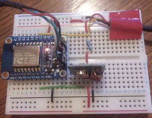
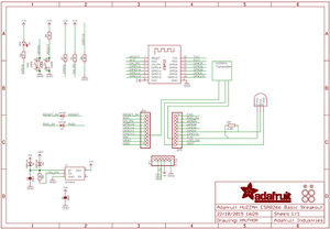
I've hacked a quick note of our development schematic and a photo - we've also got code running for air temperature, humidity, light level and pH.
You can see our code at https://github.com/hamishcunningham/fishy-wifi/tree/master/ardesp/waterelf
Let me know what you think of this approach, I'm confident it is the best way forward even for you on a tight timescale.
---
Tom Griffing
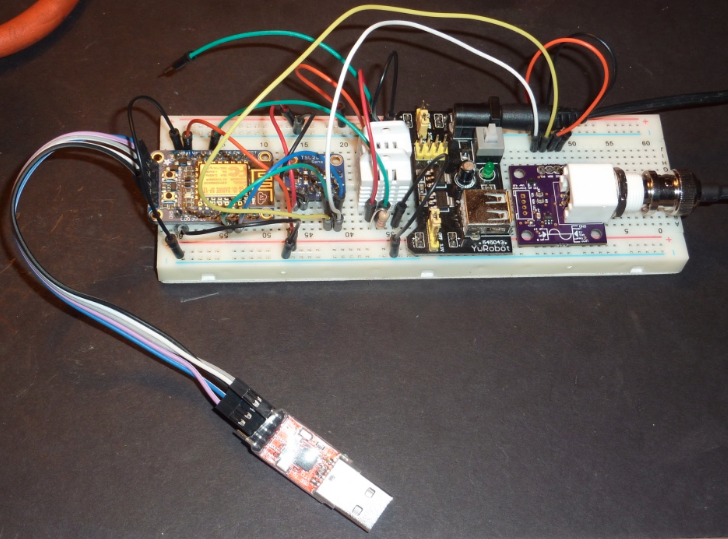
I hope I have reached the right guy . . . Marcin from OSE asked me to write about the WaterElf hardware we are using in our Aquaponics Greenhouse.
I have a question: Will it support more than one temperature / humidity sensor?
I have tried adding the second sensor, but don't know where to connect it for proper recognition. It produces output like this: Sensor Data
   { "timestamp": 37970, "airTemp": 23.50, "humidity": 55.10, "lux": 231, "pH": 7.06 }
   { "timestamp": 34994, "airTemp": 23.50, "humidity": 55.00, "lux": 232, "pH": 7.04 }
   { "timestamp": 32124, "airTemp": 23.50, "humidity": 55.80, "lux": 232, "pH": 7.04 }
   { "timestamp": 29251, "airTemp": 23.50, "humidity": 55.10, "lux": 232, "pH": 7.04 }
   { "timestamp": 26319, "airTemp": 23.50, "humidity": 55.60, "lux": 232, "pH": 7.04 }
   { "timestamp": 23271, "airTemp": 23.50, "humidity": 56.30, "lux": 232, "pH": 7.03 }
   { "timestamp": 20320, "airTemp": 23.50, "humidity": 56.60, "lux": 233, "pH": 7.04 }
   { "timestamp": 17322, "airTemp": 23.50, "humidity": 55.70, "lux": 235, "pH": 7.02 }
   { "timestamp": 14322, "airTemp": 23.50, "humidity": 54.80, "lux": 233, "pH": 7.01 }
   { "timestamp": 11395, "airTemp": 23.50, "humidity": 54.90, "lux": 239, "pH": 7.05 }
   { "timestamp": 8503, "airTemp": 23.50, "humidity": 55.00, "lux": 230, "pH": 7.00 }
   { "timestamp": 5590, "airTemp": 23.50, "humidity": 55.30, "lux": 231, "pH": 7.02 }
Gareth
Hiya Tom
Great news that you build the water elf and it all works for you.
We haven't designed in the ability to use more than one humidity/temp sensor yet, but I'm sure it could be done.
There is some interesting discussion here: http://forum.arduino.cc/index.php?topic=217689.0
Are you a software person or are you working with one?
The basic outline of what to do to add a second sensor option to waterelf.ino:
Add lines like 101 and 102 to create a second (or third..) DHT sensor (unique name)
487-494 could either be adapted gracefully to look for multiple sensors, or just duplicated with the second sensor name.
Likewise 539-540, 589-594, 613-623, could be adapted or just duplicated to cope with multiple sensors.
Each sensor needs its own pin, this is defined in line 101. You need a pin that's not in use by anything else, like 12 or 14 maybe?
Hope that helps, let me know if you need more specific advice...
Kind regards
Gareth
OSE IOT Build Instructions
Note the green wire at the top that is unplugged - it is for the second temperature / humidity sensor.
Step 1: Solder header pins to breakout board, lux sensor and PH sensor
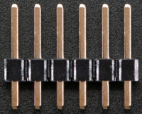
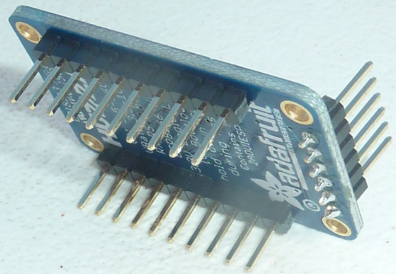
The parts come with header pins, as in the image below:
The headers will have more pins, so cut them into three pieces: Two 10 pin pieces and one 6 pin piece, then solder into the breakout board as shown below:
If you need a "refresher" for this, here is a quick tutorial on soldering the header pins to a circuit board:
Soldering tutorial for headers
IMPORTANT: The pins must be straight (perpendicular to board) while soldering. It can be aligned by inserting pins into a breadboard while soldering.
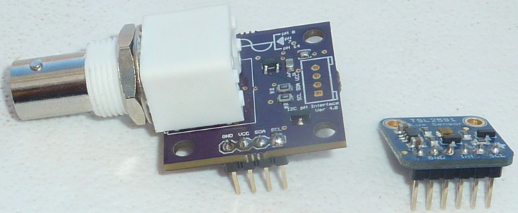
Similarly, cut and solder the 4 pin and 6 pin headers into the PH sensor and light sensor boards:
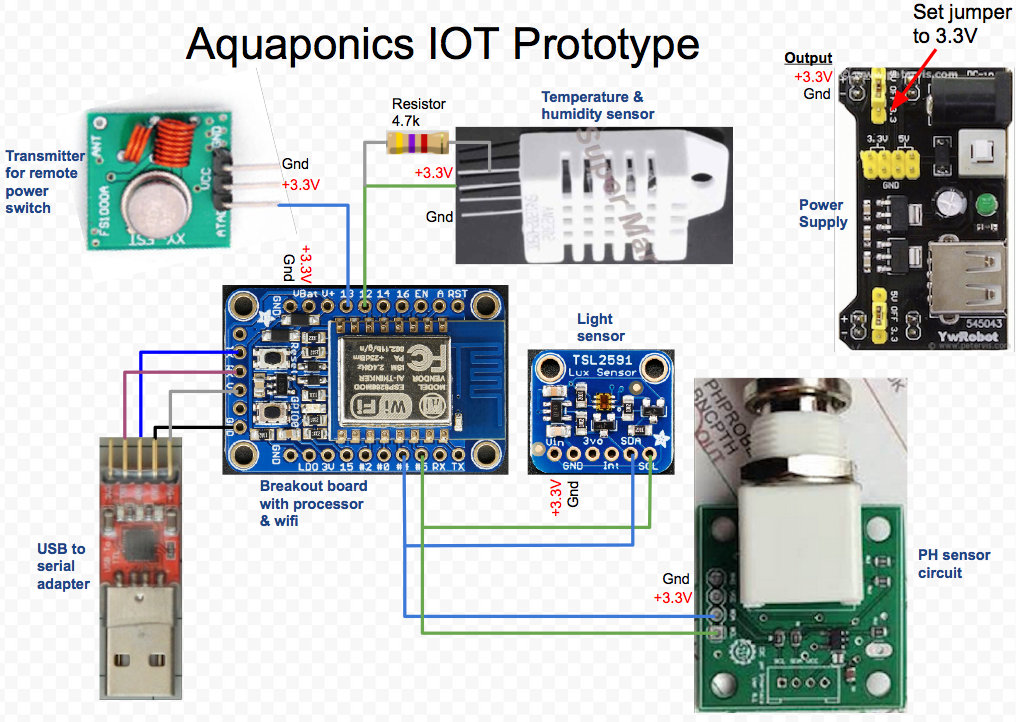
Signal Connection Diagram
The following diagram details the IOT components and connections:
Source: https://docs.google.com/drawings/d/1L-Y78PIcCsJJJHOwAnznzOVca-_7ry5qOOjC-4Ju4sI
OSE IOT Alternative
A proposed alternative to the above IOT implementation is detailed in the following document to address the expanded sensor and control requirements.
https://docs.google.com/presentation/d/1R53T4Q20qmECRlnM5jgyZy9zNYhWfWuzjP6wy15XBRg
