CEB Press/Manufacturing Instructions/Detroit Fab Lab Solenoid Driver v4
Jump to navigation
Jump to search
Source File Repository:
All source files are located in this repository: schematics, board layout, netlist, drill list, arduino source code, etc.
https://github.com/dwiel/ose-cebpress-controller-board
Goals
- Add Left/Right/Up/Down buttons on board
- Add Left/Right/Up/Down terminal positions for external control
- Add Left/Right/Up/Down to source code
- Build schematic and board layout in with KiCAD
Design Rational
- Buttons and terminals must all be easy to access
- Circuit board must be easy to etch by hand
- Populating and soldering parts of the circuit board should be easy
- Using more through hole components this time for this reason
- Circuit board should be small so that they are cheaper and faster to etch/mill
Results
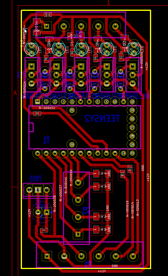
Here is a view of the board with all of the layers visible. You will want to use other views for milling or etching. Other file formats can be found in the [1].
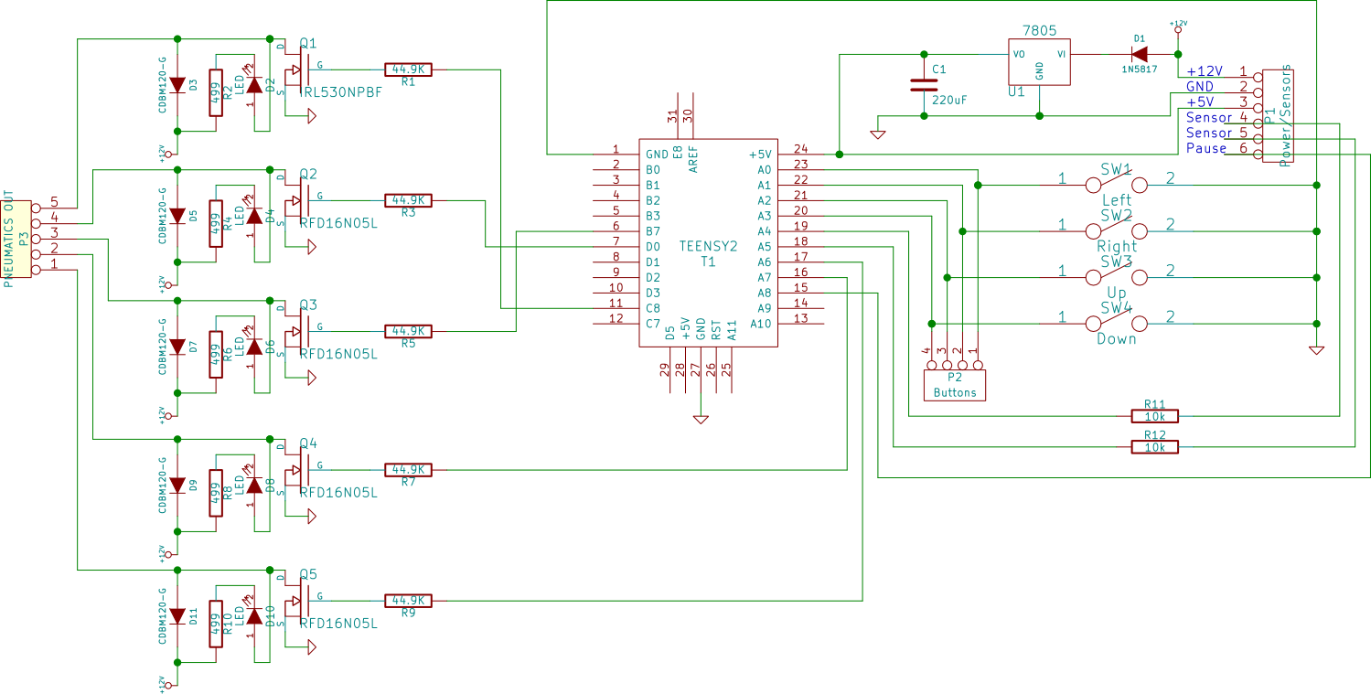
Here is a view of the schematic

In order to build this board, you will need to either:
- purchase an already milled board
- mill your own board
- etch your own board
From there you will need to assemble the board with the following parts:
Bill Of Materials
- 1x - LM7805 - http://www.digikey.com/product-detail/en/MC7805CTG/MC7805CTGOS-ND/919333
- 1x - Capacitor 220uF - http://www.digikey.com/product-detail/en/ECA-0JM221/P5112-ND/244971
- 1x - 1N5817 - http://www.digikey.com/product-detail/en/MBR0540/MBR0540CT-ND/3042807
- 5x - Resistor 44.9k ohm - http://www.digikey.com/product-detail/en/RNF18FTD49K9/RNF18FTD49K9CT-ND/2022675
- 5x - Resistor 499 ohm - http://www.digikey.com/product-detail/en/RC1206FR-07499RL/311-499FRCT-ND/731891?cur=USD
- 5x - LED - http://www.digikey.com/product-detail/en/WP3A8HD/754-1218-ND/1747617
- 5x - CDBM120-G - http://www.digikey.com/product-detail/en/CDBM120-G/641-1324-1-ND/1979689
- 2x - Resistor 10k ohm - http://search.digikey.com/scripts/DkSearch/dksus.dll?Detail&name=311-10.0KFRCT-ND
- 1x - 6 Position Header Block - http://www.digikey.com/product-detail/en/OSTTC060162/ED2604-ND/614553
- 1x - 5 Position Header Block - http://www.digikey.com/product-search/en?x=0&y=0&lang=en&site=us&KeyWords=ed2603-nd
- 1x - 4 Position Header Block - http://www.digikey.com/product-detail/en/OSTTC040162/ED2602-ND/614551
- 3x - SPDT Toggle Switch - http://www.digikey.com/scripts/DkSearch/dksus.dll?WT.z_header=search_go&lang=en&keywords=eg2388-nd&x=0&y=0&cur=USD
- 4x - SPST Tactile Switch - http://www.digikey.com/product-detail/en/MJTP1141/679-2421-ND/1798005
Notes
- The original MOSFET is rated to 50V,16A but the solenoids listed in the Bill of Materials only use 3A @ 12v (D05S-2C-12D-35 and D05S-2H-12D-35) reference pdf.
- Pullup resistor for buttons can be set in code - http://arduino.cc/en/Tutorial/DigitalPins
- The Teensy 2.0 is used in this project, but only after we realized that it uses a closed source bootloader. I'm not sure what a good long term solution is. Should we stick with Arduino Uno?
- Yes --Yoonseo
- I agree, though I won't have time to update the board, the schematic shouldn't really have to change and if we don't worry about board size laying out a new board should be pretty quick --zdwiel
- The part of the circuit with the 44.9kohm pull down resistors needs to be revised, right? Instead of in-line it should be a separate parallel path to GND
