CEB Press/Manufacturing Instructions/Mount Solenoid Valve Set And Controller Box
Jump to navigation
Jump to search
1 Video
See the full CEB Press Assembly Video for mouning of valves.
1 Tools
- Various Wrenches
1 Materials
- 3/4" Quick Coupler Set (1)
- SAE 12M to 3/4" Swivel (2)
- SAE 6M to 1/2" Swivel (6)
- Bolts and nuts for mounting on valve mount and controller
- 3/4"x1.5" Bolts (4)
- 3/4" Nuts (4)
- Prepared Controller Box
- Prepared Controller Mount
- Prepared Valve Mount
1 Steps
2 Install Controller=
- Bolt Controller Box to Controller Mount
- Bolt controller mount to CEB.
2 Mount Sensors and Magnets
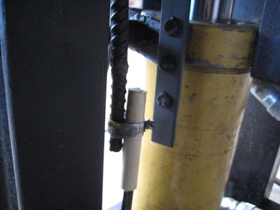
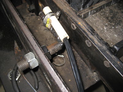
- Powerclamp the sensor that has its orange (signal) wire in Arduino pin A0 (aka pin 14) next to the primary cylinder bar. Attach 3 magnets to the primary cylinder bar such that they are vertically aligned and their terminals are reversing ex. NSN or SNS. Space the magnets approximately 5cm apart. Change the magnet positions during testing to achieve the desired soil loading position, maximum compression position, and press foot ejection position.
- Powerclamp the sensor that has its orange (signal) wire in Arduino pin A1 (aka pin 15) next to the secondary cylinder and soil loading drawer. Attach 3 magnets to the soil loading drawer such that they are vertically aligned and their terminals are reversing ex. NSN or SNS. Space the magnets approximately 5cm apart. Change the magnet positions during testing to achieve the desired soil loading position, compression position, and maximum ejection position.
The sensor is a Melexis US1881 which is a latching type. Its electrical output switches ON when a North magnetic pole is facing the lettered side of the device, and it stays ON when the magnet has passed by. It then takes a South magnetic pole to switch the device OFF, and it stays OFF when the second magnet has passed by. The device turns ON again when facing the third magnet's North magnetic pole. That is why the 3 magnets must be mounted on the bar in alternating sequence NSN or SNS.
2 Prepare Solenoid
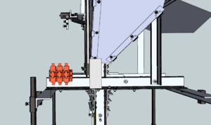
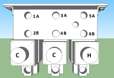
- Install the solenoid valves on the manifold in the order C-C-H, going from left to right, with the ports at the top.
- Install the quick connect inlet and outlet in the side ports on the manifold. DON'T use thread tape for any connections to the manifold.
- Onto the top of the manifold, install the 6 compression fittings into the A and B.
2 Install Solenoid on machine
- Bolt the solenoid to the valve mount.
- Bolt the solenoid and valve mount to the primary arms on the assembled CEB.
- Attach hoses from cylinders and shaker to manifold. See illustration for number locations.
- 1=Main Cylinder Top
- 2=Main Cylinder Bottom
- 3=Secondary Cylinder Tee
- 4=Secondary Cylinder Control Valve
- 5=Shaker Forward Line
- 6=Shaker Return Line (Side with Needle Valve and Tee)


