CNC Torch Table Z Height Control

Automatic capacitive sensing version of CNC Torch Table Height Controller
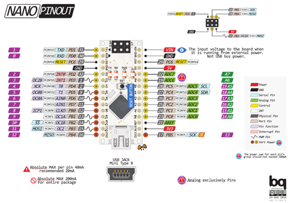
This is the automatic height levelling version based on the new TorchHeightCTRL_V.02 pcb. (All Sources on GitHub: [[1]])
Design rationale
The new pcb is an all-in-one board, that adds some peripheral interfaces to the application, like for endstop or a future direct user interface (Display).
In the automated version the 0mm-distance / start-position should be found automatically by homing. From this it will take a sample and then goes to 30mm height and take another sample for calibration. Then it will go into a loop and trying to balance the distance around a pre-set default-value of 15mm. But if you then push the button of the jogwheel you switch from autobalancing- into manual-mode and change this 15mm-default-value by turning the jogwheel. Pushing again switches back into autobalancing mode.
BOM
| Quantity | Part | Supplier | Cost |
|---|---|---|---|
| 1 | Arduino Nano V3 with USB-cable | [2] | $5 |
| 1 | TB6600 stepper driver | [3] | $8 |
| 1 | KY-040 Rotary Encoder | [4] | $2 |
| 1 | Knob for rotary encoder (must be 3d-printed on your own !!!) | [5] | 3D printed |
| 1 | Power-Supply | [6] | $27 |
| 1 | Stepper Motor 17HS19-2004S, Nema17, with 2A and 59Ncm holding torque | [7] | $16 |
| 1 | Mechanical EndStop | [8] | $1 |
| 1 | Sensor-probe | to be selfmade, from a thick piece of copper wire and a BNC-cable (but a commercial version also exists) | |
| 1 | 5-pole DuPont connector breadbord-ribbon-cable, female2male, for the rotary encoder | [9] | $2 |
| 1 | 1-pole DuPont connector breadbord-ribbon-cable, female2female, for elongate the SW-pin and connect it to the ICSP-port of the Arduino Nano. | [10] | $2 |
| 1 | 4-pole DuPont connector breadbord-ribbon-cable, male2male, for the TB6600 | [11] | $2 |
| 1 | D3D universal axis, as testrig or torch-mount | [12] | $34 |
| 1 | TorchHeightCTRL_V.02 pcb | can be ordered from Aisler as readymade project [13] (but you have to register there to see the project) | $20 |
| Set | Set of electronic parts for soldering on the pcb | can be ordered from Mouser as readymade projec01t24 and can be accessed at [14] (there you have to type in as project-key 64fff8ecbf) (edit: you have to register at Mouser to get the right formular-input-page for typing in the project-key) | $20 |
Wiring Schema

Power Supply
Warning: The phoenix-contact powersupply connector has NOT the same configuration than the connector of the same type on RAMPS-boards !!!
Dont use the plug of a powersupply that was previously configured for use with a RAMPS-board and has 2 x 12V. The TorchHeightCTRL_V02 board has 1 x 5V and 1 x 12V and will be blown immedately if you give 12V to the 5V line !!!
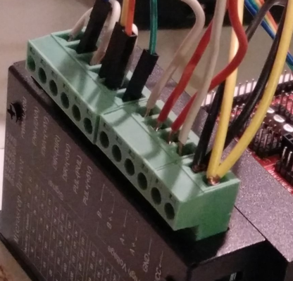
- Wiring PowerSupply
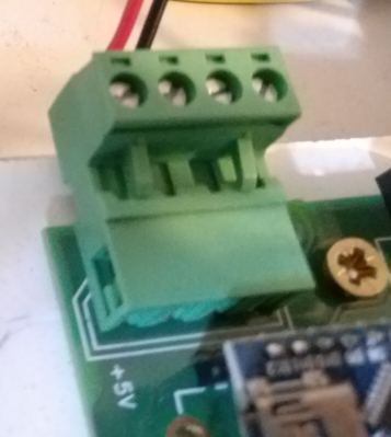
Connect 5V (red) and GND (black) from a PC-powersupply to the Phoenix Contact connector on the pcb as shown in the picture. Its a 4-pole connector, but leave two pins not connected (these are normally for 12V but its better to connect the TB6600 directly with the 12V)

Use another string from the Powersupply and connect a 12V line directly with the TB6600, with 12V (yellow) to VCC and GND (black) to GND)


TB6600
The TB6600 gets connected to J3 on the TorchHeightCTRL_V.02 pcb.
- Wiring TB6600
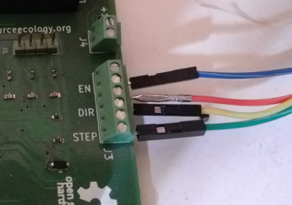
Connections from J3 to the TB6600: EN (blue) goes to ENA+(+5V), DIR (yellow) to DIR+(+5V), STEP (green) to PUL+(+5V) and one of the GNDs (orange; third pin from left to right on J3) to PUL-(PUL).
It doesnt matter, which GND-pin you use, but make sure that on TB6600-side the remaining GND-pins are bridged/connected with the GND-pin that connects to J3. Here the pin ENA-(ENA) is bridged to DIR-(DIR) and then a second bridge goes from DIR-(DIR) to PUL-(PUL), which contains also the (orange) wire that connects to one GND on J3.

The switches-setup in a configuration for 1/8 microstepping with a 2.0 Ampere steppermotor


The steppermotor pins on the TB6600 are labeled as B-, B+, A-, A+. I found, that at least for my motor the order must be B-, B+, A+, A-. Otherwise the motor is doing funny things. This may be different on other motors, but you can simply try it by exchanging A+ with A- or B+ with B -. See also the motor diagramm on [15].
The power lines should be connected directly with a 12V line of the powersuplly, as mentioned above.
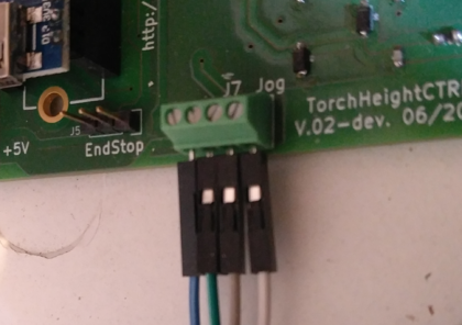
Rotary Encoder KY-040
The Rotary Eccoder pins GND, 5V, DT and CLK get connected with J7 on the pcb. If you turn the pcb that you can read the labl "J7 Jog" in the right orientation the pins on J7 are (from left to right): 5V, GND, DT, CLK.
There is one more pin on the KY-040, labelled as "SW". This is a button-press-funktion. Unfortunately the pcb-design was initially intended for another type of rotary encoder, which had not this function, so its not incorporated in the original design. But there is however a workaround (without soldering) for now. The SW pin must be connected to one pin of the ICSP-port on top of the Arduino Nano. (Note: This pin is also part of the UEXT-port, which is not used now. But later we should replace it with another free pin, e.g. pin D9.)
- Wiring KY-040
J7, from left to right: 5V, GND, DT, CLK
See the 6-pole ICSP-port on top of the Arduino Nano. The most right pin in the top row, denoted as "18, PB4, pcint4, MISO", has to be connected with the pin SW on the KY-040


EndStop
The mechanical EndStop gets connected to J5 on the PCB. The Pinout of J5 is (from left to right): GND, DATA, 5V. (Note that some commercial EndStops may have a different pinout ! You then have to reconfigure the DuPont-connector.)
- EndStop
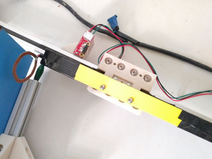
EndStop mounted to testrig
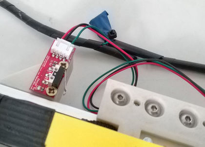
CloseUp


Capacitance-Sensor-Probe
The SensorHead-Probe gets connected with a coaxial cable with BNC-connector, where the Sensing-Ring is connected to the inner wire. You can get an impression on how the probe is made from the video at [16].
For getting reasonable signal quality, its important to connect the metal-plate (your workpiece) and also the metal-parts of the test-rig with the SHIELD-ground from the sensor-probe. This is the internal shield-pin of the AD7747 and this is NOT (!!!) identical with the overall GND of the pcb. Therefore it is connected seperately. (Note: In a possible next generation/iteration of the pcb there should become definitely an extra screw-terminal connector with about 3 or 4 SHIELD-ground pins implemented.)
- Wiring Sensor-Probe
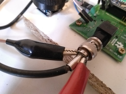
SHIELD-ground can be obtained from the wire mesh shield or from the outer metal-parts of the BNC connector.

Firmware
Switching modes
The arduino firmware is kept as small and simple as possible and should therefore be easily adoptable to daily needs - whatever may turnout to be useful in the future practical work with the torchtable. But from here and as a starting point the programm-logic suggest a workflow, that is based on two modi:
- the manual mode (where the height can be steered manually by turning a jog-wheel)
- the "auto-balancing" mode (meaning: automatical height-adaption based on capacitance-sensing data)
- See testing-video on youtube [17].
Calibration
When the program starts, there is an initiation phase used for the individual calibration of each run, like:
- do a homing and therefore get your zero-position (using a mechanical endstop)
- step upwards to a distance of 30mm and get your maximum height position (by counting steps) and measure the according capacitance value.
- adjust the working-height automatically by counting steps to a default value (lets say 15mm)
Manual mode
Then the Mainloop starts, in the manual mode. Height is not changed, unless you turn the wheel. If you do so, you can re-adjust the working height to a new level, higher or deeper.
If you press the Jogwheel down (like a button) you generally switch between the both modes. If you are currently in the manual mode, you will enter the auto-balancing mode (and vice versa).
Autobalancing-mode
The autobalancing runs in a loop (until the jogwheel will be pressed again):
- measure capacitance data
- calculate the deviation from the wanted working height
- initiate a number of (motor-)steps to produce a correction-move
Filters
There are several places in the sourcecode, where filters and algorithms can be applied, either to achieve a better signal-quality, or influence the "behavior" of the overall-workflow, e.g. like the sensivity. You can define a certain range (e.g. plus or minus 2 aF) in which you consider an deviations as artifcats and dont react with a move. Otherwise you would never have a calm position but instead a jitter of doing permanently correction moves, even if the height of the underlying workpiece doesnt have changed. More about this on the discussion page [18].
Communication
Serial output by USB-cable. This can be used for debugging while development, or in normal use transmit current capacitance-data to a host-monitoring programm on your desktop PC, that samples and visualizes graphically the height-levels of the run.
It is also planned to communicate to a direct user interface (OLED keypad) by (software) I2C.
Source
Latest Arduino-Code on Github: [19]
Optimizations
- List of possible optimizations coould be done to improve the signal [20]
- List of optimizations and fixes that definitely should be done in a possible next iteration of the TorchHeightCTRL-pcb design: [21]
- Maybe remove the need for a 5V charger? Can the whole circuit run on 12V? (<-- nope. The Atmel Atmega328 cpu needs 1.8 to 5V, see specs at [22]. If you would feed the Nano with 12V you would only burn more energy on the 78M05 voltage regulator onboard.)
Kicad pcb layout
See how to load the pcb sources from Github and into Kicad (using OSE Linux (or others)) on this instructional youtube-video: https://www.youtube.com/watch?v=v-nhG5vuZW0
The single steps are:
- Start OSE Linux
- open a shell and type: cd /tmp
- There type: git clone https://github.com/case06/TorchHeightCTRL
- open Kicad and choose from the file menu "open project".
- in the upcoming mask go to and open /tmp/TorchHeightCTRL/torchctrl.pro
- in the top icon-bar of the project-window press the most left icon "Schematic editor".
- Probably a error-msg concerning a "linear.lib" occures, press "ok" and ignore it.
- In the upcoming scheme-editor window press on the right side of the top icon bar the second last icon "Start pcb-new"
- In the upcoming pcblayout-editor choose "3D-viewer" from the edit-menu.
Outlook, Next Iteration V.03
Todo-List:
- the SW-pin of the rotary encoder for the button-pressed-function should be directly implemented into the pcb. Mounting it on the ICSP-port of the nano was just a workaround because when i first made the design i ommitted it because i had another type of rotary encoder in mind which had no SW-pin. But now it should be integrated in the pcb.
- J4 could/should be replaced with a bigger sized version of the phoenix connector. The smaller one was just simply a mistake of me, because it is rated only for a max. of 6A. I mean, we dont use it anyway now because we connect the TB6600 directly with the powersupply, but if we ever want to use it AND if you want to put more than just one Motor onto the driver (or if we simply want to use bigger motors) then 6A may be not sufficient.
- add some terminals for shield-ground, for connecting crocodile clamps (very important for reducing electrical noise !!!)
- make all J3, J4, J7 larger? They are too small, needs a special screwdriver.
Manual adjustable version of CNC Torch Table Height Controller
This is a simple POC-version that allows a manual adjustment of the Z height by turning a jog wheel (see demonstration video on youtube: [23]). The wheel can be 3d-printed [24] and is connected to a rotary encoder of type KY-040.
- manually steered height control
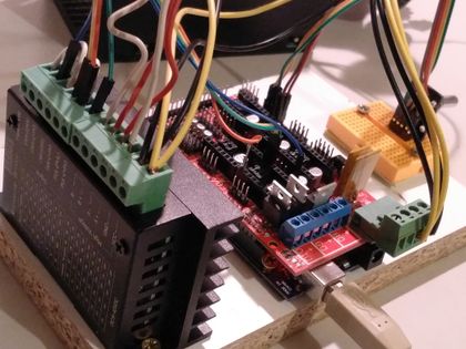
TB6600, Arduino_Mega/Ramps, KY-040 rotary encoder
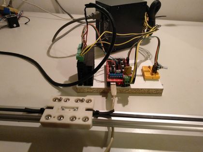
stepper driven lineardrive


- demonstration video on youtube: [25]
Design Rationale
With this rig it should be possible to manually operate the torch table height by following its slowly moving and regulate the height personally. This can be useful even if in the full version there is a capacitive sensor doing automatically that task, but one may use it then for setting the starting height or use it in other applications where a frequent manual control is an appreciated option.
The rotary encoder gives up to 20 pulses per revolution to an Arduino-Mega, which translates it into a number of motor steps and triggers these by a TB6600-based stepper-driver. A RAMPS 1.4 may act as a connection layer on top of the Arduino, but can also be omitted. We will show here which pins to wire on the Arduino and on the Ramps as well.
The firmware consist only of a few lines of Arduino-code, which makes it easy to extend and modify.
BOM
| Quantity | Part | Supplier |
|---|---|---|
| 1 | Arduino Mega 2560 | [26] or under Linux the CHG340-version: [27] |
| 1 | Ramps 1.4 | [28] |
| 1 | TB6600 stepper driver | [29] |
| 1 | KY-040 Rotary Encoder | [30] |
| 1 | Power-Supply | [31] |
| 1 | Stepper Motor 17HS19-2004S, Nema17, with 2A and 59Ncm holding torque | [32] |
| 1 | 5-pole DuPont connector breadbord-ribbon-cable, male2male | [33] |
| 1 | 5-pole DuPont connector breadbord-ribbon-cable, female2female | [34] |
Wiring
There are 3 kind of connections:
- Power-supply to Ramps/Arduino
- Rotary Encoder to Ramps/Arduino
- TB6600 to Ramps/Arduino
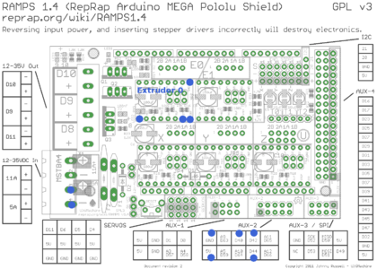
Ramps-pins to connect are marked with a blue point
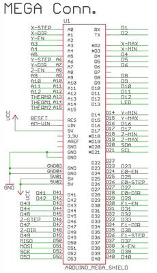
Mapping of the Ramps-Pins onto the Arduino-Mega ports
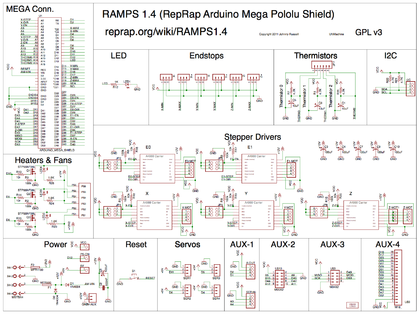
The whole Ramps 1.4 schematic


Power-supply to Ramps/Arduino
- Ramps: Connect a 12V/5A-Line to the MSTBA4-Port an the Ramps, by using a phoenix-contact plug. This will provide power for Motor as well as board-power for the Arduino-Mega.
- Arduino standalone: The Arduino musst be supplied with 5V to 12V. This can be done by the USB-connection to a desktop-pc or by a standard wall-wart ac/dc-adaptor (5V, 2A) for the Mega.
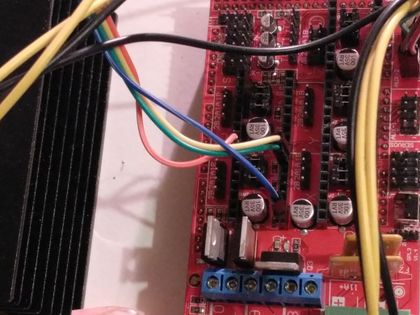
RotaryEncoder to Ramps/Arduino
The KY-040 RotaryEncoder has 5 Lines: GND, +5V, SW, DT, CLK. Connect these either to the AUX2 port of the Ramps, or directly to the corresponding digital I/O ports on the Arduino-Mega.
- GND --> GND
- 5V --> 5V
- SW --> D44
- DT --> D42
- CLK --> D40
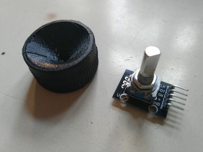
KY-040 RotaryEncoder with 3d-printed jog-wheel
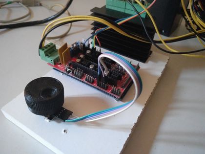
The pins at the AUX2 port are conected to the rotary encoder


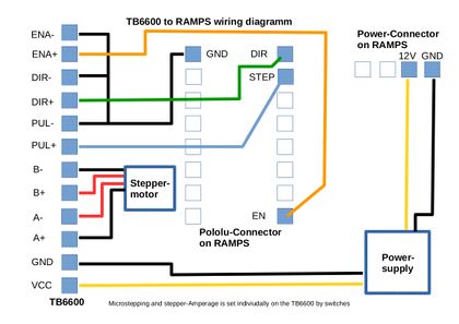
TB6600 to Ramps/Arduino, Motor and Power
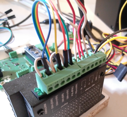
The TB6600 stepper driverhas three phoenix contact like connectors,
- one 6-pin to the Ramps
- one 4-pin to the motor
- one 2 pin to power-supply
KY-040 RotaryEncoder with 3d-printed jog-wheel. Note that the stepper driver DIR pin faces away from the power plug of the RAMPS.

The 6-pin connector has the lines ENA-, ENA+, DIR-, DIR+, PUL-, PUL+.
Make a bridge between ENA- and DIR-, together with a second bridge from DIR- to PUL-. The PUL- contains a second cable which goes towards GND on the Ramps Extruder E0 port. So in total there are 4 wires going either to the Ramps or directly to the Arduino-Mega:
1. Ramps:
- ENA+ --> EN
- DIR+ --> DIR
- PUL+ --> STEP
- PUL- --> GND
2. Arduino-Mega:
- ENA+ --> D24
- DIR+ --> D28
- PUL+ --> D26
- PUL- --> GND
upper left corner: 2 white cables make a bridge between ENA-, PUL- DIR-. The PUL- contains an additional cable (orange) that connects to GND on the Extruder E0 port of the Ramps/Arduino
The pins at the extruder E0 port are connected to the TB6600


The 4-pin connector has the lines A+, A-, B+, B-.
In the case of a bipolar stepper motor with 4 wires two of them are the ends of one coil. Connect them like this:

![[15]](http://opensourceecology.org/wiki/File:Os_manthc_stepper_wiring1.png)
An example for a tested Nema17-stepper with 2A and 59Ncm holding torque is the 17HS19-2004S, see [35], [36].
The 2-pin connector has the lines 12V+, 12V-.
Connect these to a power-supply which can deliver at least 5A. The TB6600 stepper driver is rated for up to 4A and 9-36V DC. That means you can instead of 12V also connect 24V or more towards it.
Troubleshooting
helpful document on basic stuff: https://www.omc-stepperonline.com/download/DM542T.pdf
See page 10 for a general troubleshooting FAQ
Firmware
Arduino-Code on Github: [37]