Cold Saw/V1 Design Rationale/Blade Rotation System/Drive
Notes
In order to achieve straight cuts, axis of rotation should be perpendicular to the plane of the cut. Solution is to surface grind the part that the blade presses against.
In order to protect the operator from high-speed flying chips, the blade should rotate away from the operator at the point of contact with the material being cut.
In order to prevent blade slippage, torque transmission from the hydraulic motor shaft to the blade should be mechanically supported. Solution is to insert pins into the blade that also go into a part that is strongly connected to the hydraulic motor shaft.
Hydraulic motors provide high torque and low speed operation without a gearbox
Conceptualize
Parts
Comments
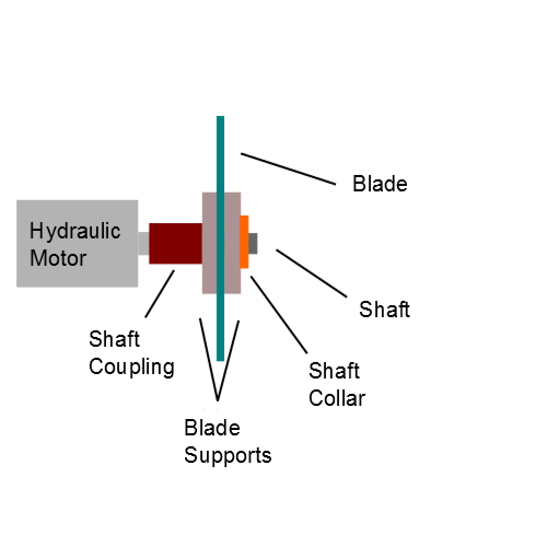
Because direct drive is used, a shaft coupling can be directly mounted onto the shaft of the hydraulic motor. The shaft coupling is held to the hydraulic motor shaft by a set screw.
A precise rod is inserted into the other end of the shaft coupling; this rod allows the other components to be mounted precisely at the center of the axis of rotation. The rod is held inside the shaft coupling by a small bolt that is tightened with a nut on the other side.
A large diameter mounting disc (a large thin cylinder) is welded onto the rod end of the shaft coupling at a precise angle perpendicular to the axis of rotation such that the blade is precisely perpendicular to the axis of rotation as well if the blade is pressed against the mount disc.
Another mount disc is mounted into the rod after the blade so that the blade is supported from both ends by a mount disc.
Both mount discs have a pinhole pattern that matches the pinhole pattern on the blade. Small rods are inserted into the matched pinholes such that high torque can be transmitted from the hydraulic motor shaft to the shaft coupling to the welded mount disc to the blade- without slipping. The pins are held by split pins at each end.
A shaft collar is mounted onto the rod after the second mount disc. The shaft collar is held onto the rod by 4 setscrews. The shaft collar exerts force on the non-welded mount disc through 4 setscrews; the pressing force is transmitted from the shaft collar to the non-welded mount disc to the blade. The blade becomes precisely pressed against the welded mount disc.
