Hole Puncher Calculations
Overview
 Ironworker Hole puncher calculations.
Calculations
Force Required to Shear the metal
According to an Ironworker Blade manufacturer (he prefers not to be mentioned by name) with a 6 degree rake in the blade, you can shear 1"x10" steel with 100 tons of force.
No data has been found regarding how much force to shear 1"x12" as is the desired spec for the machine, so we will assume that there is a direct relaitonship between length of cut and force to shear it. Following this logic, 100T/10"=xT/12" Solving for x, we get Force to shear 1"x12"=120T.
We will include a safety factor to account for any errors we have made. A force of 130T or more should suffice.
The required moment to act on blade
To find this, we must make a few basic assumptions:
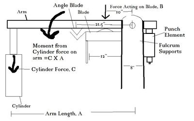
- The fulcrum supports are 8" wide
- The blade is 12" wide and placed as close as possible to the fulcrum supports.
- The force will be applied at the center of the blade and distributed evenly.
- The angle blade, and the flat blade are mounted on the same mount.
Blade moment
Since the force on the blade(B) is known, as is its distance from the fulcrum, we can calculate the necessary moment, M. M=Force(B) x Distance from the pivot(d) (10")
For the capability of cutting 1"x12", B=130 tons.
- M=130 tons x 10" = 1300 inch tons
Throw Requirements
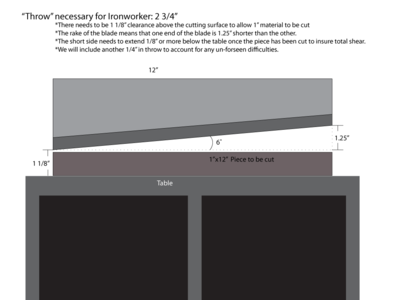
Throw is the vertical movement required for the blade. In this case, It's 2.75".
Calculating the arm length and cylinder size
The arm length will control how many times magnification we get from the cylinder force.
- If building an ironworker whose max cutting ability is under 1" x 12", you could scale the cylinder size down according to your desires.
Since the such high force is required to shear the desired metal, we will use the 6" bore cylinder with a 12" stroke available at surplus center.
Arm length must satisfy throw and force requirements. Force generates a minimum arm length requirement, whereas throw generates a maximum arm length.
- Throw requires that the cylinder rod is long enough, or spaced properly, so that the blade has enough vertical movement. This is effected adversely by arm length. IE, the longer the arm is, the longer rod you will need.
- Force requires that the lever arm is long enough to magnify the force from the cylinder to enough to shear the metal. The longer the arm is, the less force you will need.
Minimum Arm Length
To calculate the arm length using this cylinder, we must set the cylinder force (C) multiplied by the lever arm length (A) equal to the required moment (M), so A X C = M. Solving for A, we get A=M/C
In this particular design, the cylinder will be contracting while shearing, which means the cylinder tonnage we are using must be on the contracting side. See Cylinder Tonnage Calculations for how to find the contracting strength. The calculated contracting tonnage (C) for this specific cylinder is 31.8 tons.
So, A= 1300inT/31.8T =
A =40.86" Minimum.
Maximum Arm Length
This is calculated by the ratios of throw to rod length and arm length. The distance (D) any point on the arm travels is inversley related to its distance (L) from the fulcrum. Or: D1/L1=D2/L2. 1 corresponds to the cylinder, and 2 corresponds to the blade. L1=12", as it is the rod length on the cylinder. L2=2.75", as it is the required throw for the blade. D2 is 10", the distance from the blade to the fulcrum. D1 is unknown.
Solving for D1, we get D1= D2L1/L2= 10"*12"/2.75"= 43.63"=A max
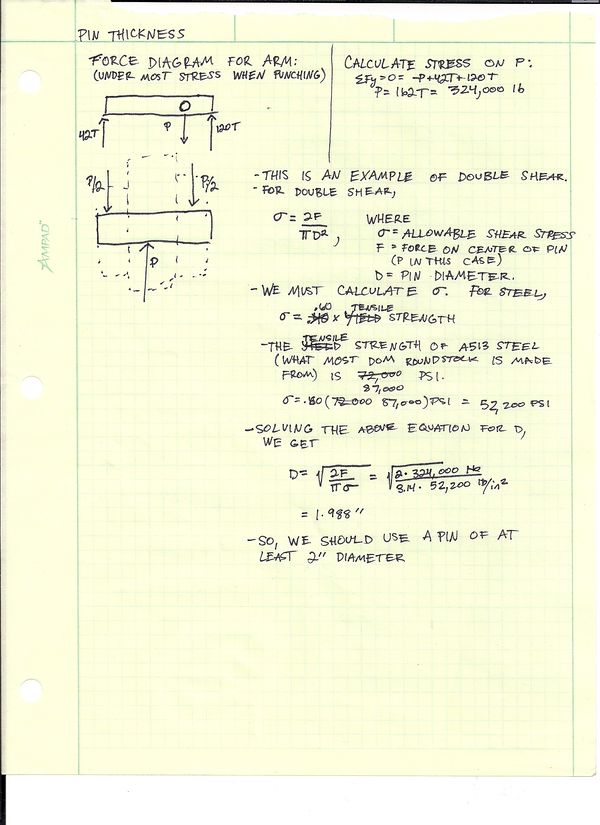
Calculation of the size of the pin
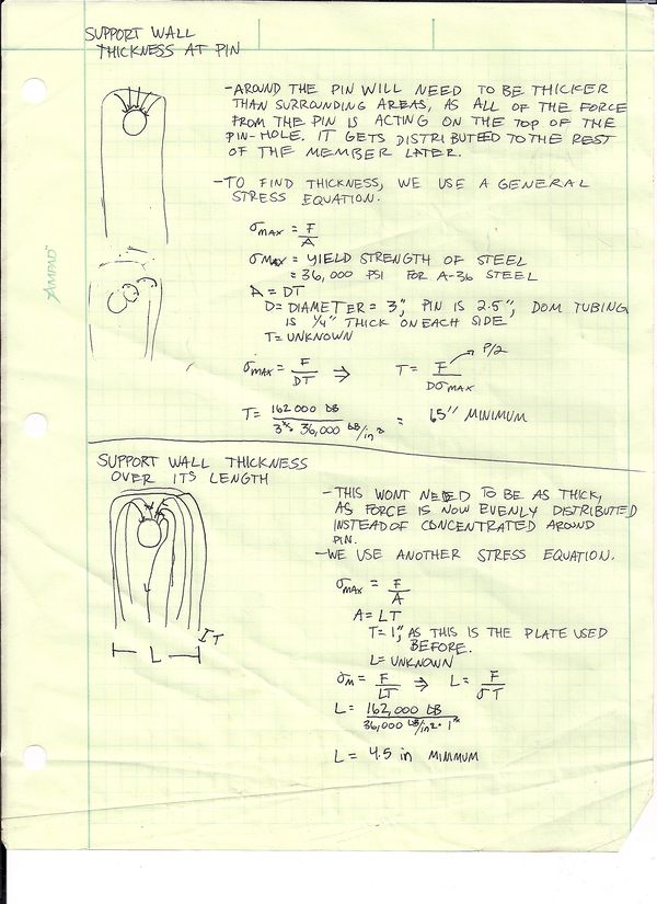
Vertical Support Thicknesses
Arm Thickness
Since the arm is absorbing twice the force from the pin as the Vertical Supports, It needs to be twice as thick, or 3" thick.
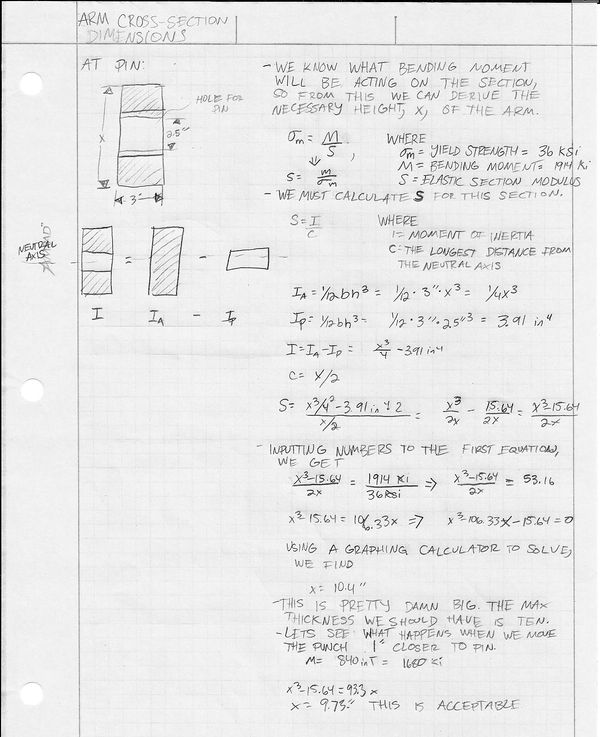
Arm Dimensions
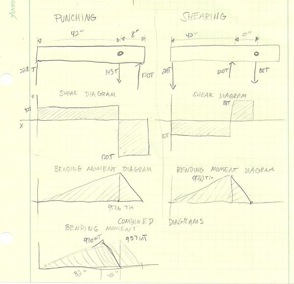
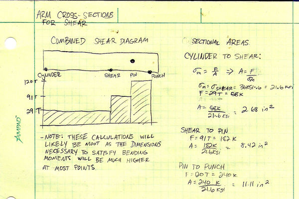
Making shear and bending moment diagrams will help us determine how thick the arm should be at various locations.
