Industrial Robot Systems Engineering Diagram
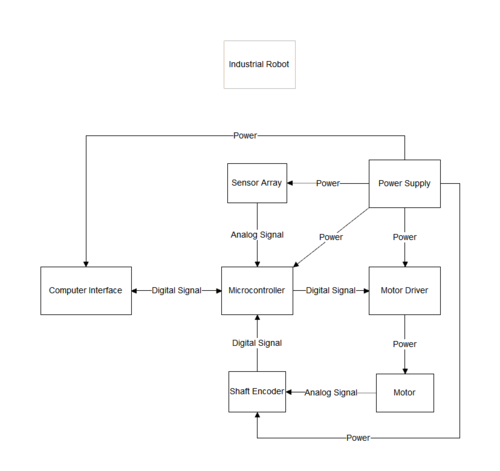
To start, the power supply takes electrical power from external sources and feeds current at different voltages to the various parts of the industrial robot. Particularly, the sensor array, which can be comprised of different devices such as lasers to determine distance, generally uses a small voltage and perceives the surroundings of the industrial robot; this information is transmitted as an analog signal to the microcontroller; the microcontroller takes this analog signal and converts it to a digital signal using an analog-to-digital converter contained within. Using these digital signals as well as those from the computer interface (human-controlled programming allows various functions and movements to be recorded in the memory of the microcontroller), the microcontroller sends digital signals to the motor driver, which transmits differing levels of electrical power to the motors according to the microcontroller's command. As the motors rotate their shafts, a shaft encoder analyzes the specific speed of the shaft rotation (perceived as an analog signal) and transmits this information to the microcontroller as a digital signal; this shaft speed information allows the microcontroller to compensate for differing loads on the motors hence control the actual motor shaft movement with a high degree of accuracy; this feedback structure is known as a closed-loop control system.
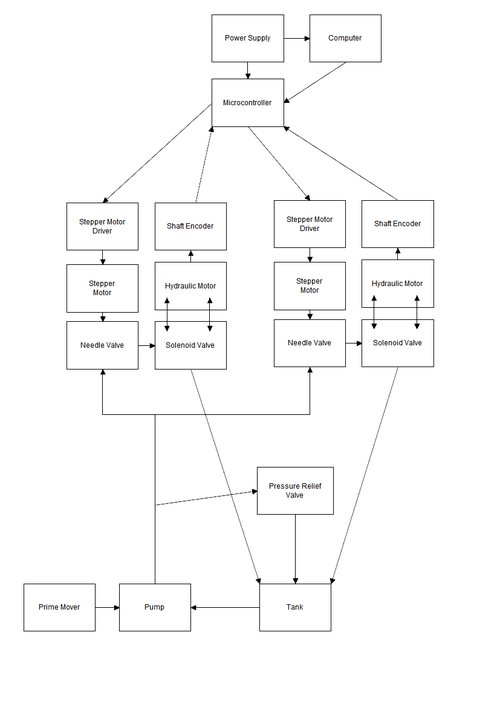
This is a diagram for the industrial robot with hydraulic drive, where 2 of the 6 motor systems are portrayed; note that this is rough and might be missing the answer to key concerns such as pressure regulation and additional safety valves, or using suboptimal design pieces, ex. using a servo instead of stepper motors might be better. Initially, the prime mover operates the hydraulic pump and the power supply energizes the computer and microcontroller (also the shaft encoder and motor drivers, but the lines are missing). At the robot's neutral position, the needle valves are closed, hence continuity of flow is maintained solely by the fluid moving through the pressure relief valve. When the computer outputs gcode, the microcontroller reads it then powers the solenoids to achieve a desired flow direction and issues digital signal commands to the motor drivers. The motor drivers respond to these signals by giving a corresponding electric current to the stepper motors; in turn, the stepper motors turn and opens the needle valve in discrete increments (steps), with which flow is controlled. Now the hydraulic fluid can enter through the needle valve and rotate the hydraulic motor either clockwise or counter-clockwise depending on the position of the solenoid valve. The shaft encoder then measures the rotation of the hydraulic motor shaft and sends this information to the microcontroller; the microcontroller responds by increasing or decreasing flow to the corresponding hydraulic motor (through motor driver then stepper motor then needle valve) in order to maintain a desirable actual speed of shaft rotation.

