LifeTrac III Definitions
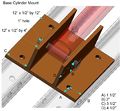
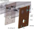
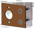
Defining each indivisible piece of a machine is the first step in the Distributed Collaboration process. The key is that each definition is broken up into "self-evident" units. In short, "self-evident" means that all the information an experienced fabricator would need to make the piece is present in a single file.
It is important not to shoehorn information into the definition that is not strictly necessary. The definition files need to be kept small and limited so that they are easy to change later. If a single tube needs to be made 6" longer and one of the holes moved 6", then only one definition should change and it should be as simple as spitting out a new illustration with slightly different labels on it. If nothing else about the design of the machine is affected by that change, then the definition file can be replaced without changing anything else, even if the machine is well into development and the project and report phases are already humming along. The project step that refers to making that piece won't change because all it said to do was "cut to length" and "drill holes." That the length and hole position changed is irrelevant to the instructions that refer to the definition. In this way changes to the machine design are kept as low-cost (in terms of documentation) as possible. Additionally, even major forkings of the machine design are possible with minimum effort.
Also, whenever possible the definition file should be structured such that it requires no translation between languages. Or, if it does require translation, the words should be simple and unambiguous. Numbers are the best. If they aren't enough on their own, then simple labels like letters are acceptable. If actual words are necessary, then they should be generally accepted terms like "bearing" or "valve."
The best approach is to keep the entire design of the machine in one set of units. You CAN convert the units into their counterparts in another system of measure, but it isn't going to be of much help. For example, the LifeTrac is designed around 4" square tubes. If someone wants to build the LifeTrac with metric parts they are going to have to redesign pretty much all of the measurements because they will be using square tubes that come in round metric numbers, which means all the bolt holes will be offset slightly. This unfortunate situation means that a metric version of the LifeTrac will have to exist side-by-side with an imperial version. They will have to be independent machines. Mixing the designs up together will only create confusion and unnecessary work.
