MicroTrac 2015
Video
Development
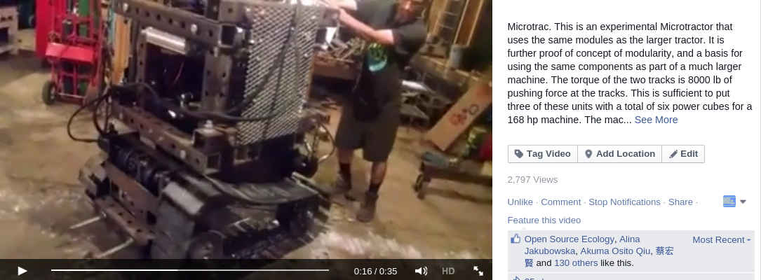
Results - July 2015
https://www.facebook.com/OpenSourceEcology/videos/vb.66469461561/10154088233271562/?type=2&theater
Introduction
Prototype 2 of the MicroTrac. See Power Cube Genealogy for Power Cube.
Working Document
Parts Library
Power Cube v7s
| Component Area | Part | Qty | Price | Weight |
|---|---|---|---|---|
| Cage | Hydraulic Pump .677 cu in, 10.1 gmp @3600 RPM, 3000 PSI max, 4000 RPM max | 1 | $185 | 9 lbs |
| Cage | NT filter or SC filter | 1 | $17 | 2 lbs |
| Cage | or type E coupler half 1/4" key 2.5" o'all long | 2 | $9.86 | 1 lbs |
| Control | 3 spool valve (about 1900-3400 PSI relief setting) | 1 | $220 | 35 lbs |
| Drive Wheel | 1 | |||
| 17.5 HP gas engine | 1 | 60 lbs | ||
| Hydraulic Reservoir | 1 | 10 lbs | ||
| Battery | 1 | $23 | 20 lbs | |
| Frame Metal | 2x2x1/8" square tube 29" long | 6 | $30.95 | 44 lbs |
| Frame Metal | 2x2" square tube 24" long | 4 | $17 | 24 lbs |
| Frame Metal | 2x2" square tube 20" long | 8 | $28.46 | 40 lbs |
| Frame Metal | 2x2" square tube 7" long | 2 | $2.49 | 4 lbs |
| Frame Metal | 7x25" plate 1/4" thick | 1 | ||
| Optional/Unused | L095 coupler half 1" shaft 1/4" key 1-1/16" long | 1 | $15.28 | 1 lbs |
| Optional/Unused | L095 hytex coupler insert | 1 | $18.29 | 0 lbs |
| Optional/Unused | L095 coupler half 3/4" shaft 3/16" key 1-1/16" long or 5/8" | 1 | $15.28 | 1 lbs |
| Total | $582 | 251 lbs | ||
Design
Goals
- 41" (1041.4mm) width
- 54" height
Design Proposals
Tracks with rotors
draft File:Ose-microtrac-20150429.skp
- laying out ideas for idler and motor
PC7s Modification Suggestions
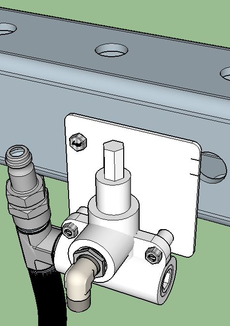
- Separate mount for the pressure relief valve and output port. This mounts the pressure relief valve and output port so the port is facing up and the hose has only a gradual 90 degree bend, with full 3/4" plumbing to the port:
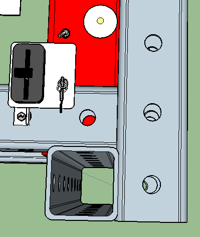
- Split the controls apart from the hydraulic connections. This will separate the throttle and keyswitch into a control panel that can be easily relocated anywhere on the PC7s frame. This will allow all controls for to be grouped together. The hydraulic connections can be streamlined for more direct fluid flow and thus less energy loss.
Here is a suggested panel for PC7s controls:
Note also that the gas filler cap has been moved nearer the center of the tank to reduce leaking due to sloshing.
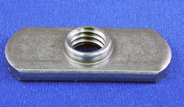
- Several items will need to be connected to the frame that do not require full structural strength (ex: Control Panel & Output Pane). Bolting these to the frame are a challenge using conventional nut and bolt hardware. It is simplified by using special nuts with conventional bolts, such as the one shown below:
Source: ND Weld Nut
These are intended to be welded, but should work in this application without welding.
Past Design Work
Tracks
Track Proposal Google Drive Folder
Reference Works
Toro makes a series of comparable machines, called the "Dingo". Toro publishes information about them, which make excellent references into their design and operation:
Toro uses a dual gear pump in Model 323, directly coupled to the engine shaft. One pump is 4 GPM and the other is 10.8 GPM. It can switch from one pump to the other for higher speed or higher torque. They say the low flow setting is good for training.
They use two hubs and two rubber disc couplers for power transmission - we haven't use this setup, but I've seen them before
http://www.dingo.com.au/dingo-design/dingo-male-mount-plate/


