Micro Power Cube
Overview
Test Run
Test Run with Tractor
Power Cute 2?
Files
- Sketchup Runtime (free version): Sketchup Make
- Micro Power Cube Model: File:Micropc.skp
- Micro Power Cube Model - Ver 8: File:Micropc v8.skp
- DXF CAM files for plates - File:MuPC.zip
- Toronto Course Presentation: File:Micropc Presentation.odp MPC Presentation
Electric Motors
The first generation of the Micro Power Cube used a 3 phase DC motor typically used in remote control airplanes:
- 1.94hp - $50 - RC Motor
While the motor was small, powerful and efficient, it required regulated DC power to operate. The available power supplies for this application were very expensive and physically too big to fit in the 1' cube. We opted for a power supply with half the power capability (1000 watts instead of 2000 watts). It was small enough to fit and it worked well.
The second generation employs an AC motor from common vacuum cleaners. They are rated at 12 Amps (1440 Watts, or ~1.9 HP), but they don't require a separate power supply. In addition, the motors are readily available in upright vacuum cleaners. The motors usually operate at high RPM (~ 30,000 RPM), but have strong bearings meant to handle the lateral force of driving a belt. One concern about them is heat, as they are relatively inefficient and usually have a lot of air flow through the windings. Luckily, vacuum cleaner motors often come with a device that shuts off the electricity in case of overheating.
Fabrication
The Modules of the Micro Power Cube are:
- Frame
- Motor Assembly
- Hydraulic Assembly
- Shaft Drive Power Unit
- Filter
- Pipes
- Connectors
These modules can be fabricated separately, then integrated for the final assembly.
Frame
Motor Assembly
Hydraulic Assembly
Communications
From Stefan:
I remember mentioning "brushless outrunners". A cheap source is Hobbyking (They also have US warehouses but it's not immediately obvious how to order from them):
http://hobbyking.com/hobbyking/store/__517__59__Electric_Motors-Outrunners_by_size.html
These motors have no mechanical commutator and need a driver:
http://hobbyking.com/hobbyking/store/__61__182__Speed_Controllers-All_Speed_Controllers.html
These RC drivers are controlled like any RC servo which means you can use the Arduino servo example to get started.
Tom Griffing
Marcin Feedback
Tom,
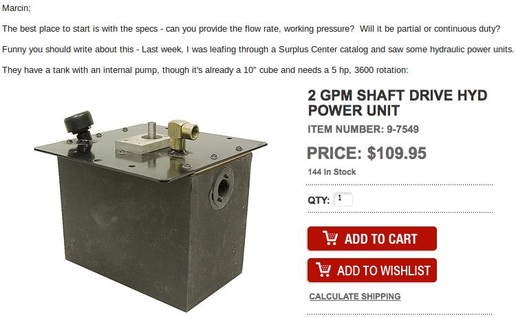
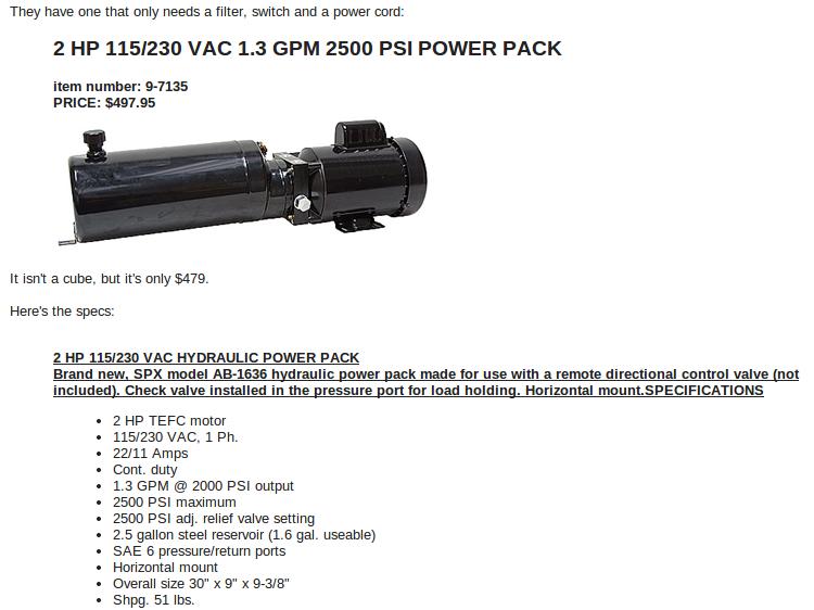
It appears that the industry standard is dunking the hydraulic pump right in the reservoir. How Clever!
You are right about requirements. Here they are:
- Audience: the hacker in a hackerspace who wants to add hydraulic power to their skillset, or the custom fabricator or any producer looking for a small hydraulic power solution.
- External electric source
- Entire assembly is one cubic foot or less
- Weight is under 25 lbs
- May be used for powering LifeTrac and in shearing 1"x8" slabs of mild steel with an Ironworker machine.
- GPM - 1
- Reservoir - 1 gallon
For the elite hacker crowd, I think making this thing as small as possible would make it not only more manageable but also less intimidating.
I imagine the first option above ($109) with a tiny 2 kW electric motor, with 4x geardown, so that it's matched to driving the motor, but at slightly reduced output. The main challenge will be to not burn out the electric motor.
See this motor - [1]. Motor needs a driver and controller to run - see comment from Stefan above.
Motor RPM is 9120 at 24V from its specs. If the above hydraulic unit without motor is designed for 5 hp drive at 3600 RPM - we have only 2kW =2.7 hp - or about half the required power. So to not burn out the electric motor, we want gear reduction factor of 9120/3600 x2 = 5.1 gear reduction.
If the power unit costs $109 minus the driving motor - motor is $41 + controller + geardown - should be around $300 total.
MJ
Can we do this?
- - - - -
I think so, but it will take some adjustments.
The reservoir above ($110) will work. It is geared to deliver 2 GPM at 5 HP, so running it at half that power should deliver 1 GPM (2000 Watts / 746 = 2.68 HP).
I'll have to investigate the motor ($41), as I have concerns about startup torque, as it is purposed for low-torque applications - even if geared 3:1. The hydraulic pump requires the most torque at start-up (extra torque for spin-up to operating speed and hydraulic fluid is thick when cold).
The controller ($100) is the smallest offered with 90A capability (actually: 100A). I have an Arduino development kit for stepper motors and have used it to drive various motors, but at less than 10A. I'd suggest replacing it with a 120 VAC motor if possible (no power supply or controller needed). I'll look into both options.
The power supply should deliver 22 - 30 Volts @ 90A. For size and weight, it should be a switching power supply. 24V is a common voltage and I've found a lot of them, but only one capable of 90A. It's looks big, heavy and costs $200. I'll look for other options. [2]
The filter ($12) is the smallest offered by Surplus Center.
Belt, pulleys, hydraulic connections to be added.
- PARTS -
Power One 12V, 50 / 100A or 24V 50A 2000W Dual Output DC Power Supply 110 / 220V $199.99
2 GPM SHAFT DRIVE HYD POWER UNIT item number: 9-7549 PRICE: $109.95
3/8" NPT 7 GPM RETURN LINE FILTER item number: 9-7291 PRICE: $11.95
NTM Prop Drive 50-60 Series 380KV / 2665W
Turnigy Super Brain 100A Brushless ESC Speed Controller
I'll keep looking.
Tom
Design
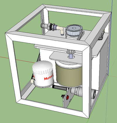
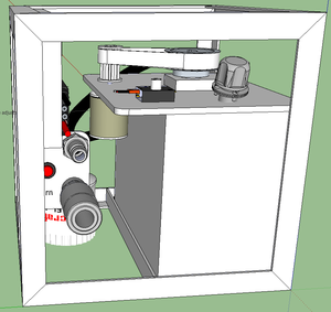
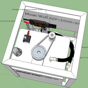
I've done a Sketchup of the initial design, for reference.
Frame
All angle iron is 1" x 1" x 1/8", welded together.
Power Unit
The tank / pump has a 10" x 10" plate on top and 2" must be removed from one edge before assembly.
Pullies
The "gearpully" style pulleys and belt should be researched to insure they are capable of sustained 2 HP power transmission.
Update: GlobalIndustrial.com sells a widef variety of "Timing Belts & Pulleys" and I am searching to find a set that will perform better.
Power Supply
The dimensions of the larger power supplies are an issue, as is the cost. Many of the RC motors use 22 Volts, so I will look only at 24V power supplies. Here is dimensions and prices of some commonly available:
SE-1000-24: 1000W, $185, 10.9" L x 5" W x 2.5" H SE-1500-24: 1500W, $279, 10.9" L x 6.9" W x 2.5" H (no space for this model)
I've re-designed the power cube with a 24V, 1000W power supply and I had to move things around a lot go get it to fit. 1000 Watts is 1.34 HP.
I also changed the design for the lower power output. The pump unit is meant to be driven by a 5 hp motor, yet we are using a 2 kw motor, but driving it with 1000 Watts max. The horsepower output will be:
1000 Watts / (746 Watts/HP) = 1.34 HP
The torque required for the power unit is for 5 HP directly. Since we will be using less power, we can "gear down" the motor to deliver the torque of a 5 HP motor, but at a lower speed. Use the HP ratio to derive the ratio teeth in the gearbeltpulley, with the smaller gear at 10 teeth:
5 HP / 1.34 HP = 3.73
3.73 * 10 teeth =~ 37 teeth
Checking with Grainger, they sell a gearbeltpulley with 36 teeth (close enough).
My only concern not is if the gearbelt can handle the power and speed.
OK ... I found a power supply that will fit completely inside the frame, is cheaper and puts out more power:
MaxAmps
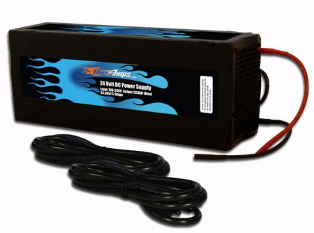
The only caveat is that it is thicker and would make assembly difficult, if not impossible.
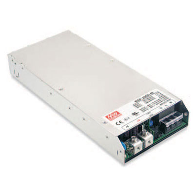
OK ... I think I've found one by the same maker, the Meanwell RSP-1000-24, available from Jameco: Mean Well 1000W power supply
They also have one with twice the power (and twice the price) in the same size case, the Mean Well RSP-2000-24: Mean Well 2000W power supply
Motor
Ideally, we'd like a motor to deliver max power at 10,000 RPM, as the desired gear ratio is 3:1 (Motor:Pump). These RC motors are rated in RPM/Volt. Higher values yield lower torque. The motor originally suggested is rated at 2000 Watts at 22 Volts. This is more power than can be delivered by standard 120V connections, which have max amperage of 15A (15A x 120V = 1800W). The motor position can be moved along the edge of the reservoir - it should be placed to accommodate a commonly available belt. The motor mounting should be adjustable to adjust for tensioning of the belt.
ESC
The ESC (Electronic Speed Controller) should be capable of driving the motor at the rated current plus some reserve current capacity.
Next, we need a "driver" circuit to send the necessary control signal to the ESC. The signal should be a PWM (Pulse Width Modulated) signal with period of 20 ms and positive pulse varying between 1 ms and 2 ms as follows:
1.0 ms - OFF
1.5 ms - Half speed
2.0 ms - Full speed
Some specs say that the pulse width should vary between 0.8 ms and 2.2 ms. This is probably safe for good measure, as we will set it once for full speed and forget about the range.
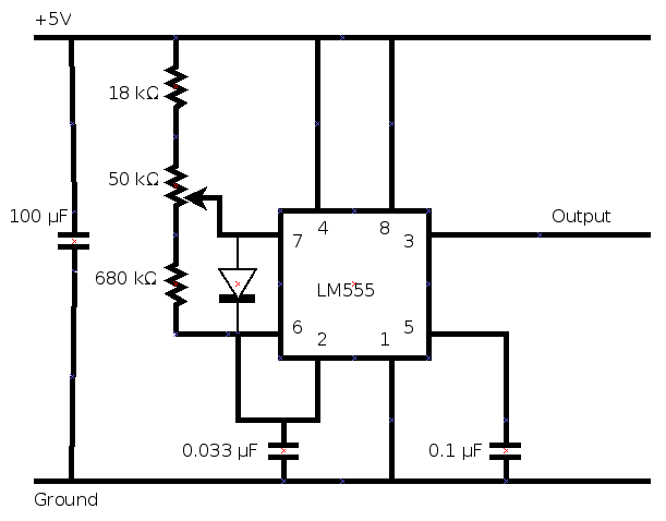
The ESC driver circuit will be something like this:
Update: I found cheap "Servo Testers" on HobbyKing.com for driving the ESC Controller, so we'll use them instead. They're very cheap and are available from the same supplier as the motors.
FILES
I've completed the drawing and the BOM and it will cost more than initially projected - around $550 in parts alone. Here is the Sketchup drawing and the BOM:
File:Micro Power Cube V1.1.skp
File:Micro Power Cube BOM V1.1.pdf
Prototype 1
Built the Micro Power Cube in 8 days, including ordering parts and waiting for parts to arrive.
Drove to Missouri with Micro Power Cube and ran a successful test - moving a CEB Press cylinder up/down, punching holes in 1/8", 1/4" and 1/2" steel. It was then connected to a LifeTrac VII and successfully drove it at 1/6 MPH for 30 seconds.
Here is a video summarizing the results of the test with the hole punch: [3]
In this test, the Micro Power Cube was used to power the LifeTrac tractor. It was slow, but it worked: [4]
The testing revealed two "glitches":
1. The rubber belt had a partial failure when driving a large cylinder, with pressure relief set to maximum and cylinder hit its limit of travel. This demanded the maximum available power and caused 6 teeth to be ripped from the face of the belt. This failure was expected, as the belt delivered was weaker than expected. Other sources of stronger belts are being researched.
2. The power supply shut down twice, after its rated power had been exceeded. After removing electricity, it resumed normal operation. This can be mitigated by adjusting the pressure relief valve to lower the maximum pressure.
Conclusion: The weak spot is the belt and all issues can be resolved by decreasing the setting on the pressure relief valve.
Prototype 2
For the second prototype, I will be using a motor, power cord and power switch from a vacuum cleaner I found at a nearby sale. The label on the vacuum boasted 11 amps and we can calculate power in Watts and in Horsepower as follows:
11 Amps x 120 Volts = 1320 Watts
1320 Watts / (746 Watts / HP) =~ 1.77 HP
12 Amps x 120 Volts = 1440 Watts
1440 Watts / (746 Watts / HP) =~ 1.93 HP
The pump expects 5 HP at 3600 RPM, and with the horsepower above, we can calculate the pulley sizes from motor to hydraulic pump, beginning with a 10 tooth pulley as follows:
Ratio = 5 / 1.77 hp = 2.82
PulleyP = PulleyM * Ratio = 10 * 2.82 teeth = 28.2 teeth
For a 12 Amp motor, this comes to 1.93 HP, Ratio: 2.59 or 10:26 teeth
Let's check the RPM numbers. Vacuum cleaners run at high RPMs (often around 10,000 RPM) and since I don't have the exact number for my motor, I'll use 10,000 RPM as follows:
10,000 RPM / 2.82 = 3546 RPM
Close enough. Now to find pulleys and a transmission belt.
Communications
Power Cube Query
Ralph;
Thanks for the contact.
Many of the machines in the OSE lineup are are powered by hydraulic fluid and OSE has relied on gasoline engines for driving hydraulic power units for power delivery.
The new project that I have prototyped is an electrically-powered hydraulic power unit called the "Micro Power Cube":
The design uses an RC motor to drive a hydraulic pump (submerged in the fluid reservoir) to pump hydraulic fluid to "quick connect" couplers which allow it to be connected to a variety of hydralulic machines.
Here is the design review for "Prototype 1": http://www.youtube.com/watch?v=W9eBID_TJtE
I drove up to OSE Factor-E-Farm in Missouri to test it with various machines: https://www.youtube.com/watch?v=9bdQi8n7SBA
Here is the OSE page, describing the progress made so far: http://opensourceecology.org/wiki/Micro_Power_Cube
The power supply produces 24VDC to the ESC and motor to drive the hydraulic pump. A "Servo Tester" controls the motor speed. This much is already working.
The changes we need are in the power supply. These are the issues we have is with the "prototype 1" power supply: It probably provides more regulation than we need for driving the motor It is longer than the cube is wide and the connectors extend outside the cube frame The power produced is 1000 watts instead of the the desired 2000 watts It has a high cost / weight ratio I have begun work on a second prototype and came across a new power supply - the Mean Well RSP-2000-24. I think it resolves most of the above issues, but the cost - $449.00 + S &H. Also, looking at the photo, its dimensions may be an issue again when the output wires are connected.
The current need is for a design for a small switching power supply capable of producing 24VDC @ 83 Amps, for ~2000 Watts with an input of 120 VAC.
I haven't found any reference of how much regulation is necessary for driving the ESC controller / motor, as these motors are usually driven from batteries. I expect that it needn't be better than 5 - 10%, though as it is only meant to be switched to provide 3 phase DC pulses to the motor windings to keep the motor turning and driving the hydraulic pump.
So, the question is if anyone there could help with the design of a switching power supply?
Any help / suggestions would be greatly appreciated.
Regards,
Tom Griffing Open Source Ecology
OSE Tee Shirt Printing
On 6/14/14, 2:14 PM, Marcin Jakubowski wrote:
> People here are interested in silk screen printing our own shirts. How do you feel about making our own shirts as part of the workshop? If we have the stencil prepared, it takes minutes according to my peeps here. This is with the spirit of OSE DIY, and will cost next to nothing. We can say, BYOS. Bring your own shirt. > > MJ
Marcin;
OK. The only way I have to contact her is via the OSE Facebook page, as I don't have her contact info. I don't know if she's interested in a Micro PC or a VII PC - there's a big difference. I'll ask her for details of what she wants.
Once you have the silkscreen, printing is easy - the main cost is the shirt. One screen for the front (the badge) and a second for the back - one for the Power Cube, another for the CEB Press, etc. The "Badge" silkscreen would be the OSE logo - and could also be used to label machines, houses, boxes, etc. You could use many different color inks with the same silkscreen. Cleanup is a must, as dried ink can ruin a screen.
Here's a $199 "starter kit" with everything needed to start printing:
http://www.silkscreeningsupplies.com/product/screen-printing-starter-kit
For $210, you can buy a silkscreen printer to create your own silkscreens:
http://www.amazon.com/Provo-Craft-Novelty-yudu-62-5000/dp/B0025T6V5C
Tom
- 6/20/14 -
Marcin;
After some looking, I found some kits and suppliers that can be used without a printer. They come with photo-sensitive chemicals to create screens, some come with exposure lights (but you can use regular incandescent lights as well).
Screens can be purchased separately for around $20 each and they vary in size - up to 20" x 24" or larger. Screens can be re-used by removing an existing design and re-applying the photo-sensitive chemicals and re-exposing. The printer will limit the size of the screens - but so will your printer if using a typical 8 1/2 x 11 printer. You could get around this limitation if using a mosiaic layout with multiple smaller printouts. Do you have a larger format printer?
We'd also need transparency film for printing the images.
Silkscreeningsupplies.com has the best price ($199 + $25 S&H) on the "DIY Starter Kit", which comes with one screen and more equipment. We'd have to buy another screen to do a two-sided TeeShirt. It comes with 1 pint of the photo emulsion and emulsion remover for "erasing" a screen (normally $55.00). It comes with one 8oz ink color (black).
The "Speedball Ultimate Screen Printing Kit" is a more basic kit for $94. It comes with two screens (8.5" x 10" and 10" x 14") - which would be just right for the two-sided Tee Shirts. Making more screens would require buying more photo-sensitive chemicals (Speedball Diazo Photo Emulsion Kit - $15.56 ea). It comes with 4 - 4oz inks: Red, White, Blue and black.
I'll visit an art store to see what they have, but I'm leaning toward the $199 kit plus another screen and white ink - probably around $300 total.
Tom
Workshop Information
- Sketchup: File:Micropc.skp
- Presentation: File:Micro Power Cube.pdf
- Steel Layout File:MPC Steel.pdf
Toronto Workshop: August 8 - 10, 2014
A Micro Power Cube workshop has been scheduled in Toronto, Canada with the help of The University of Waterloo and The Diyode Community Workshop. The workshop will span 3 days and will fabricate and test Micro Power Cubes.
A Document has already been started for the workshop:
https://docs.google.com/presentation/d/1Vu26RrT3XNG-c59bcJX-QhQwWLGgeYzA6dwsXwhzmdw/edit
The workshop information has already been published on the following sites:
Website: http://opensourceecologyuw.com/workshops/
Eventbrite: https://www.eventbrite.com/e/power-cube-workshop-oseuw-tickets-12252478493
New Design
The Micro Power Cube has been re-designed with a specific motor and a new belt /pulley configuration.
Motor Selection
The motor selected for the Micro Power Cube requires the axle for the pulley to rotate clockwise. I found one motor made by "Lamb", but it rotates in the opposite direction. After reversing the wiring to the motor brushes, it rotated in the clockwise direction.
Pulley Design
Vacuum motors turn at high RPM and in normal operation, they turn the "beater bar" at 4500 RPM with the belt on the bare motor shaft and a 1 3/8" pulley on the beater bar. The motor shaft is straight, but the pulley on the beater bar is "bowed" to make the belt self-centering. In our application, the pump in the requires 3600 RPM, so we need to reduce the RPM by increasing the pulley size. We can calculate the belt speed and the new pulley diameter as follows:
Belt speed: 4500 RPM * Circumference = 4500 * 1 3/8" * 3.1415 = 19438.03 inches/min
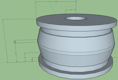
New diameter: 19438.03 / (3600 * 3.1415) = 1.71875 inches (roughly: 7/8" radius)
The pulley design is as shown below:
