Open Source Helical Piers Design Guide
Composition
- Connector Fitting and pin
- Flighting
- Shaft
Shaft First Principle Shaft Calculations
Take the area of steel in the support, and calculate compressive strength to gain a first principle idea of the performance capacity of steel posts.
- 2-7/8": Steel shaft at 2-7/8" diameter and .217 wall has about 1.8 sq in of area according to Area Calculator. J55 alloy at 55ksi means that ultimate compressive load with 0 margin of safety (see Factor of Safety) is about 100k lb.
- 2-3/8": Steel shaft at 2-3/8" diameter and .156 wall has about 1.1 sq in of area according to Area Calculator. J55 alloy at 55ksi means that ultimate compressive load is 60 klb.
- Safety factor of 4-6 [1] - 10-15 klb allowed load.
- This is consistent with the 11,000 lb holding strength of p2 posts - such as
Design Intro
From [2]
Helical piles are a factory-manufactured steel foundation system consisting of a central shaft with one or more helix-shaped bearing plates, commonly referred to as blades or flights, welded to the lead section. Extension shafts, with or without additional helix blades, are used to extend the pile to competent load-bearing soils and to achieve design depth and capacity. Brackets are used at the tops of the piles for attachment to structures, either for new construction or retrofit applications. Helical piles are advanced (screwed) into the ground with the application of torque.
The terms helical piles, screw piles, helical piers, helical anchors, helix piers, and helix anchors are often used interchangeably by specifiers. However, the term 'pier' more often refers to a helical pile loaded in axial compression, while the term 'anchor' more often refers to a helical pile loaded in axial tension.
Flight Spacing
From [3]
Helical piles are designed such that most of the axial capacity of the pile is generated through bearing of the helix blades against the soil. The helix blades are typically spaced three diameters apart along the pile shaft to prevent one blade from contributing significant stress to the bearing soil of the adjacent blade. Significant stress influence is limited to a 'bulb' of soil within about two helix diameters from the bearing surface in the axial direction and one helix diameter from the center of the pile shaft in the lateral direction. Each helix blade therefore acts independently in bearing along the pile shaft.
Interpile Spacing
Spacing should be 4x where x is the diameter of the largest helix.
From [4]
Multiple piles shall have a center to center spacing at the helix depth of at least four (4) times the diameter of the largest helix blade (ICC-ES AC358). The tops of the piles may be closer at the ground surface but installed at a batter away from each other in order to meet the spacing criteria at the helix depth. For tension applications, the uppermost helix blade shall be installed to a depth of at least twelve (12) diameters below the ground surface (ICC-ES AC358).
Shaft Capacity
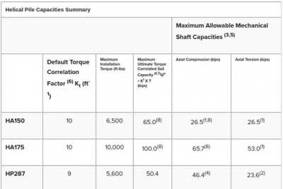
This is what the shaft can hold (assuming maximum capacity of soil), From [5]:
Ultimate Pile Capacity
- Add up the support capacity of each helix by summing (bottom area of helix *soil bearing capacity)
- soil bearing capacity is 2000 psi for clay according to some sources [6] an d 1500 psi according to others.
Plates
- Plate is determined by the way in which the beams of a foundation will be mounted.
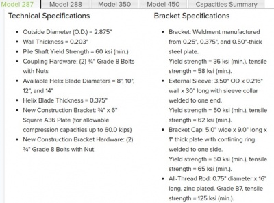
- A vertical adjust with 3/4" thick g8 threaded rod can be used. See Bracket Specifications at Open Source Helical Piers Design Guide#Shaft Capacity above.


