OSE Piping Workbench
![]() Hint: See Workbench Source Code at PVC_Pipe_and_Fittings_Library#OSE_Piping_Workbench
Hint: See Workbench Source Code at PVC_Pipe_and_Fittings_Library#OSE_Piping_Workbench
Introduction
The OSE pipe workbench is a FreeCAD workbench with pipes and fittings. It creates pipes and fitting using FreeCAD Parts workbench and Flamingo.

Installation
In a Linux system
$ mkdir -p ~/.local/share/FreeCAD/Mod
$ cd ~/.local/share/FreeCAD/Mod
$ git clone https://github.com/rkrenzler/ose-piping-workbench.git
![]() Command line instructions work on Debian 12
Command line instructions work on Debian 12
Hint:For those new to Linux, always remember Linux is case sensitive.
Pipes
The dimensions of the PVC pipes can be found here PVC_Pipe. Wikipedia on Nominal Pipe Size (NPS) [1],
A pipe is described by its outer diameter OD, its wall thickness Thk and its height[1] H.
To create a pipe, click  in OSE piping workbench. Select pipe dimensions and click "OK".

To add new dimensions adjust CSV pipe.csv in tables directory within workbench directory.
Elbows
An elbow is described by an angle alpha, outer pipe diameter POD, inner pipe diameter PID, H, J, M.
To create an elbow, click  in OSE piping workbench.


To add new elbows, adjust elbow.csv in tables directory within workbench directory.
Sweep Elbows
A sweep elbow is a special elbow with larger radius of the bent part. It is described by outer pipe diameter POD, pipe thickness PThk, G, H,and M.
To create an elbow, click  .
.


To add new sweep elbows, adjust sweep-elbow.csv in tables directory within workbench directory.
Couplings
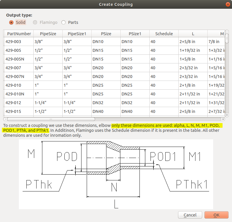
A (general) coupling is described by dimensions: POD, POD1, PID, PID1, L, M, M1, N. The dimensions POD1 and PID1 are not from a official specifications. They are derived from pipe size and schedule. In a reducer coupling, the pipe dimensions on one side POD and PID differ from on the other side POD1 and PID1.
To create a coupling, click  in OSE piping workbench.


To add new couplings, adjust coupling.csv in tables directory within workbench directory.
Bushings
![]() Hint: Correction needed from octagonal shape to hex shape bushing flange, as bushings like bolts are hexagonal.
Hint: Correction needed from octagonal shape to hex shape bushing flange, as bushings like bolts are hexagonal.
A bushing is described by dimensions N, L and pipe dimensions. As pipe dimensions we use POD, PID1, and POD1.
To create a bushing, click  in OSE piping workbench.


To add a new coupling to the part list, adjust bushing.csv in tables directory within workbench directory.
Tees
A tee is described by parameters G, G1, H, H1, M, M1, and pipe dimensions. As pipe dimensions we use POD, POD1, PID, and PID1.
To create a tee click  in OSE piping workbench.


To add a new tee to the part list, adjust tee.csv in tables directory within workbench directory.
Crosses
A cross is described by parameters G, G1, H, H1, L, L1, M, M1, and pipe dimensions. As pipe dimensions we use POD, POD1, PThk, and PThk1.
To create a tee click  in OSE piping workbench.


To add a new cross to the part list, adjust cross.csv in tables directory within workbench directory.
Corners
An corner is described by dimensions G, H, M and pipe dimensions. As pipe dimensions we use POD and PID.
To create a corner, click  in OSE piping workbench.


To add a new corner to the part list, adjust corner.csv in tables directory within workbench directory.
Customization
The dimensions of the fittings are saved in | CSV files. If you want add new dimensions or change old ones, modify tese CSV files.
The CSV files are in ~/.FreeCAD/Mod/ose-piping-workbench/tables. The columns are separted by commas ",". Always keep this format.
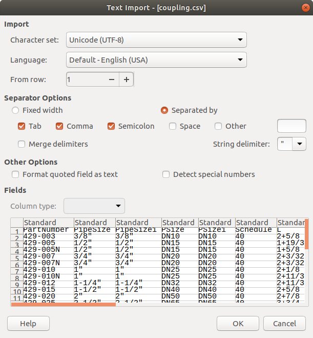
To modify CSV files with LibreOffice Calc follow these steps:
- Open CSV file in LibreOffice Calc. Calc must correctly detect the column-separator "Comma". If it does not, check "Comma" manually. Click OK.
- Now you can add, remove and modify dimensions of the fittings. Each row of the table must contain a unique part number and dimensions. You do not need to specify every dimension. To find out which dimensions are mandatory for particular part, click on a button with this part in OSE-piping-workbench. The dialog will tell you which dimensions are mandatory.
- Save the CSV file. Calc will ask you which format to use.
Select "Use Text CSV Format"


Programming
- FreeCAD scripted object
- It should be possible to represent the object with "classic" FreeCAD forms like cylinders, spheres, sweeping objects ...
- It should be possible to use solids.
- The main purpose is to create tools for moving, rotations, and fittings.
Documentation
Programming
Remarks about the coupling code
To create a simple coupling or a reduced we internally use a more general coupling. This general coupling is described by 9 dimensions: POD, PID, POD1, PID1, X1, X2, N, M, M1. The dimensions POD, PID, POD1, and PID1 are derived from the pipe sizes. The are abbreviations of Pipe Outer Diameter and Pipe Inner Diameter. The dimensions X1 and X2 are not official dimension names.

The offset a1 is calculated in such a way, that the thinest part of the middle section is not thinner than the walls on of the both sockets. Lengths a2, a3, a4 and angle b1 are derived from the dimensions and are only used to calculate a1.
Useful links
- An example of fittings with dimensioned drawings produced by Aetna lastics.
- Forum entry on freecadweb.org
Discussion
- ↑ We use height instead of length in order to make a pipe similar to a FreeCAD cylinder. These particular choice of pipe dimensions makes it more compatible with pipes from flamingo workbench.