PowerCube Engine Mounts and Hydraulic Motor Mount
Jump to navigation
Jump to search
Engine Mounts and Hydraulic Motor Mount
See Power Cube Tank Welding Procedure
Then review assembly order:
- Place the ¼” x 2” x 2” x 8” angle against the tank, 3" below the tank top and 8" from right edge of the tank as shown. Tack-weld it in place.
- Align the edges of the ¼” x 8” x 9” plate and the ¼” x 8” x 12” plate, forming a 90 degree angle as show below and weld the edge securely.

- Thread nuts on the four engine mounting bolts about 2/3 onto each bolt.
- Place engine on the 8" x 12" plate, insert the bolts into the engine mounting holes, with heads against the plate. Check for proper centering of the shaft in the hole and alignment of the bolts, then tack-weld the bolt heads to the plate. Remove engine and completely weld the bolts to the plate.
- Align the holes in the ¼” x 8” x 9” engine to those in the 29" angle iron as in the diagram below and secure with bolts, nuts and washers. Place the bolted assembly in the frame as shown and clamp to the frame in about the position shown.
- Align the holes in the ¼” x 8” x 12” engine plate to those in the 8" angle (above) and secure with two bolts, nuts and washers.
- Align the edges of the two engine plates so the corners just touch and tack the plates together.
- Tack the 29" angle iron in place to the two bottom angles.
- Attach engine.
- Check that all fits well, then weld angle iron and engine plates securely in place.

- Engine mounting
- NOTE: This may require some adaptation, as the bolt holes on engines may differ. On some Kohler engines, the bolt holes were not drilled through, but were "dead end". In this case, we had to drill matching holes in the engine plate and tap threads in the engine holes.
- Examine the engine shaft – it should be 2” long. If longer, cut the shaft to 2” long.
- Hoist the engine and center it on its mounting plate. Verify that the engine shaft extends through the hole without touching the plate.
- Thread nuts on the engine mounting bolts about 2/3 onto each bolt.
- Lift each side of the engine from the plate and insert the four engine mounting bolts in the mounting holes so the engine is supported by the bolts.
- Re-check the engine alignment on the plate, then weld the bolt heads to the engine mounting plate.

- Hydraulic Pump Mounting
- Place the engine key in the engine shaft keyway (it should fit tightly in the slot)
- Slide the larger end of the coupling on the engine shaft
- Tighten the lock screw with the appropriate hex key (ie: allen wrench).
- Bolt the hydraulic pump to the pump mounting plate using two (size) bolts and (size) nuts.
- Thread one nut on each of the four 3/4" x 4 1/2" bolts, insert the bolts through the holes on the hydraulic pump mounting plate as shown below.File:PumpBolts.jpg
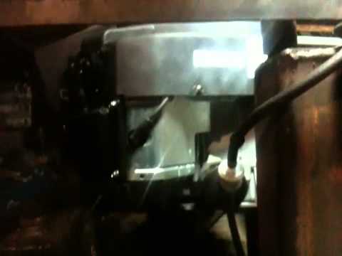
- Verify that the key is in the hydraulic pump shaft, then align it with the keyway in the coupler and slide the pump upwards until the bolt heads touch the engine mounting plate as shown below. Tighten the lock screw on the coupling with the appropriate hex key.File:PumpPlateMounting.jpg
- Align the hydraulic mounting plate so its edges are parallel with the engine plate and weld the four 3/4" bolt heads to the engine plate as shown below.File:PumpPlateWelded.jpg