Shonda Research
new data dump
tool dependency
- types of machine tools capable of being build by concrete and floating precision (spindle requirements and any other precision parts listed) (manhy of the tool description are taken from wikipedia)
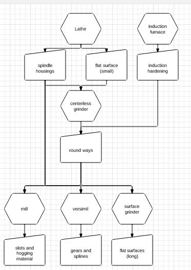
- the three basic requirements for building precice machine tools is ways for linear movement, housings for bearings and spindles, and flat matting surfaces for alignment. unfortunately to get all three of these at the required level of presision takes machine tools ... and it becomes a recursive loop. However if a purpose build temporary setup is made using dial indicators and precision levels (cheap, by first world country standards, tools) then the process can be boot strapped and one machine can make parts for a second and then between the two most other machines can be made.
- so starting with a the production of a lathe, the only precise parts are the spindle (bearings will be purchased and spindle is just a pipe, housing will be boot strapped or outsourced) and the rails (which only have to be long enough for making spindles for other machines (~2 ft travel). Once a lathe is built that can produce spindles for a centerlss grinder hardened shaft can be ground to tolerances of within a thousandth. then with spindle and way production capability a surface grinder or mill with surface grinding capability can be made. those three machines will give the three required operations of linear movement, spindles, and mating faces.
- lathe: a machine tool which rotates the workpiece on its axis to perform various operations such as cutting, sanding, knurling, drilling, or deformation with tools that are applied to the workpiece to create an object which has symmetry about an axis of rotation.
- requires: a stiff spindle(roller bearings generally) with a chuck adapter on the end, 2 axis or movement, one long way and another about ¼ the length of the long axis, a tail stock with a morse taper, a quick change gear box for threading parts (only on manuals, hybride and cnc will use tachometer and servos to thread)
- Versamil attacment for lathe: a milling head attachment for the lathe with 2 axis of movement, a vertical linear travel (Y axis) and a rotary axis around the Y axis (B axis) plus a spindle with a quick attach plate for various attacment (milling, grinding, Gear cutting, off center drilling). this allows us to (much slower), create parts of this caliber [[1]]
- requierments: a vertical axis (4 thinner ground ways mounted between plates), a motor mount with pulleys ending in a spine coupler capable of running 4 000 RPM),
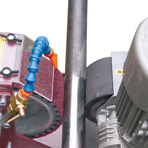
- Centerless grinder: Centerless grinding is a method of material removal through grinding [[2]], similar to centered grinding except for the absence of the spindle. It has high throughput, i.e. a large number of parts can be manufactured in a short time.
- requires: two accurate grinding spindles (4000 rpm and around 100rpm respectively), one of which should be able to rotate 10 degrees and travel to increase the diameter ground, and the ability to align both spindles and work blade along the same axis
- mill: A milling machine is a machine tool used to machine solid materials. Milling machines are often classed in two basic forms, horizontal and vertical, which refers to the orientation of the main spindle. Both types range in size from small, bench-mounted devices to room-sized machines. Unlike a drill press, which holds the workpiece stationary as the drill moves axially to penetrate the material, milling machines also move the workpiece radially against the rotating milling cutter, which cuts on its sides as well as its tip. Workpiece and cutter movement are precisely controlled to less than 0.001 in (0.025 mm), usually by means of precision ground slides and leadscrews or analogous technology. Milling machines may be manually operated, mechanically automated, or digitally automated via computer numerical control (CNC).
- requires: three axes of linear travel (2:1:1 lengths) and a spindle, aditional axis can be added for more utility and easier use.
- surface grinder: Surface grinding is used to produce a smooth finish on flat surfaces. It is a widely used abrasive machining process in which a spinning wheel covered in rough particles (grinding wheel) cuts chips of metallic or non metallic substance from a workpiece, making a face of it flat or smooth.
- some of the work that a surface grinder would do can be done with a Milling machine that can run 4000 rpm but at lower accuracy
- requires: three accurate axis, and a grinding spindle
- cylindrical grinder: The cylindrical grinder is a type of grinding machine used to shape the outside of an object. The cylindrical grinder can work on a variety of shapes, however the object must have a central axis of rotation. This includes but is not limited to such shapes as a cylinder, an ellipse, a cam, or a crankshaft
- requires: 2 axis of linear movement, one turn table, and two spindles (one lathe, one grinding)
- drillpress
- requires: quill (allows a spindle to move along its z axis while maintaining accuracy), and spindle. everything else is preference for moving tables and slides.
- bandsaw (vertical and horozontal): for cutting stock to size
- requires: heavy hindge(horizontal) or linear (vertical), and hydraulic clamps (possible autofeed of stock)
- arbor press (hand or hydraulic): for seting parts on an arbor or broaching holes, etc
- requires
links for yahoo multimachine lathe
[[5]]
- link dump for multimachine meta-project.
- taper dimension links [[6]]
- pipe schedule chart [[7]]
- Ohio source for hardened and ground shafting plain or predrilled (quote for 2X 8' long 3" O.D. 60RC rails $1500)[[12]]
- spirit level accurate to 5 ten thousandths over 10" costing $61.25 [[13]]
- original patent for concrete machine tools by Lucien yeoman (I think) [[14]]
- main site for the graphic designer for the yahoo lathe multimachine group, Tyler Disney [[15]]
Review
Chuck
21-Sep-2011
Great work, Shonda! Adding some thoughts/reactions.
- Consider building centerless grinder first. Use this to produce rails for lathe.
- If necessary, follow up the centerless grind by lapping with a ring lap. It should be possible to obtain ways with diameter consistent to a few tenths.
Lathe ways
I like the idea of adjusting two ways straight and parallel then grouting in place. The classic vee-flat ways (or round-flat) are kinematically correct. Parallel round ways are overdetermined. Nonetheless, my suggestion is to use parallel round ways but design the carriage to accommodate slight variations in way spacing.
Adjusting ways to straightness is an interesting challenge. Even a 10-second precision machinists level may not be up to the task in the vertical, and doesn't readily handle horizontal straightness. My suggestion is to go optical.
The traditional technique is autocollimation. However, I have cooked up some optical techniques based on using an ordinary consumer digital camera and software.
- as with traditional autocollimation, we need a kinematic sled that rides on the guideways (two vees on the main rail, a flat on the secondary rail), which is advanced along the rails in steps equal to the stride between the two vees.
- the sled carries a digital camera instead of a mirror.
- for one type of measurement, the camera axis is parallel to the ways and the camera is focussed on a distant fixed object (preferably through a window/door, several hundred feet away). Open-source software (e.g. openCV, ImageJ) can establish image shifts to sub-pixel accuracy. This technique can measure angular deviation to a few seconds of arc.
- for a second type of measurement, the camera overhangs the lathe bed and faces down towards the floor. At floor level there is a trough of water; the upper surface of the water reflects the image of the camera and sled. Once again, a very small tilt of the camera axis is detectable as a shift in the position of its reflected image. This measurement functions similarly to a precision level but may be more sensitive.
- in both types of measurement, an open-source computer script can handle the computations and identify the location, direction, and size of corrective movement needed to straighten the ways.
Carriage
The carriage must engage the ways with a large area of contact to ensure rigidity and good wear life. This requires an internal half-cylindrical surface accurately mated to the ways. My best idea so far is to drill a slightly undersize hole, split into halves, and finish lap to size.
Two such half-cylinders, well-spaced, could be grouted into the carriage to follow the main guideway. The second guideway would also have a half-cylinder shoe, but an intermediate flat-against-flat (or, alternatively, a "rocker") arrangement would accommodate slight variations in way spacing without disturbing main guideway tracking.
Lathe bootstrapping
It is possible to turn parts between dead centers before the headstock is built. This might be the way to turn bearing seats on the spindle.
Linear encoders
Linear encoders are expensive. Here is a possible alternative. The Trav-a-dial has been around for decades and really works. Put a rotary encoder on it and you have a high resolution linear encoder system. A grit wheel concept (like the HP drafting plotters use) might also work.

