Solar Concentrator Tube
Solar Receiver
This is further work on the solar concentrator tube (a section of the Solar Turbine project), as begun in the initial design.
A good reference on solar concentrators is found in Power From the Sun.
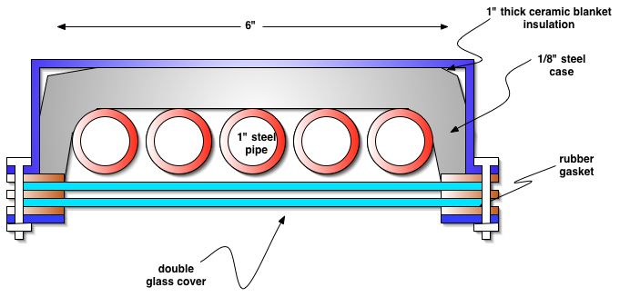
Here is a proposed design, consisting of 1", schedule 40 galvanized pipe, and ceramic fiber insulation. Basic specifications:
- 6" wide by 40 feet long
- 1" schedule 40 plumbing pipe, 5 pieces
- Double glazing, window glass
- Ceramic insulation
- Case is 1/16 or 1/8" steel
- Approximately 8 feet above reflectors
- Fixed position
- Pressure relief valve on turbine end
- Steam deliverly via 2 valves and mixing chamber
- Reflector solar intercept - 40 square meters (approx. 40 kW of thermal energy)
- Theoretical conversion from solar radiation to usable steam - 50%
- Theoretical steam generation rate - 5 lbs of steam per minute at 140 psi and 350 F
- Theoretical power output - 4 kW at overall 10% system efficiency (assumes 20% efficient steam power plant)
- Theoretical electrical output - 3.6 kW
- ~$1600 material cost for 40 kW solar concentrator system (without power plant)
Cross Section
Top View
Joints Between Sections
The collector is made of four 10' sections. They need to be connected while allowing for minimal heat loss and attachment to the solar collector frame.
Attachment to Frame
Selective Surface Coatings
Given the 6000W power loss from blackbody radiation of our collector at 200C, it is desirable to use low emissivity coatings. Solkote appears to have absorption around 90% and emissivity aroung 25%. This would reduce the blackbody radiation to 1500 W.
Thermafin has a product with absorption around 95% and emissivity at around 10% at 100C, though emissivity around our 200C of interest is not stated.
Pipe Strength
1 inch schedule 40 metal pipe, as proposed, is rated for 1800 psi at 750F - [1]
