Steam Engine Specifications/Work Diagram Construction
Jump to navigation
Jump to search
Main > Energy > Steam Engine
Construction of a Work Diagram
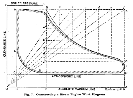
Refer to fig. 7 in "Steam Engines'
Procedure
- Determine the initial pressure, ratio of expansion, and percent of clearance.
- Draw lines OX and OY at right angles.
- Make OR the clearance displacement percent.
- Make RX the length of the stroke
- Draw RA perp. at the clearance displacement length to represent 3-8% (med. speed engine) of the total displacement.
- Draw AK at 0.98 of the boiler pressure
- Draw KX at the stroke length.
- Draw LH at 14.7 psi for atmospheric pressure.
- Locate cutoff point B for expansion ratio (1/8, 1/4, etc. of stroke len)
- Divide BK into equal distances (a,b,c, etc)..
- Connect them to point O
- Extend horizontals from the points where diagonals meet with line BP.
- Extend verticals down from (a,b,c, etc)
- Connect these points to form the expansion curve.
- Back pressue curve at FD about 2psi above atmospheric
- Compression curve at DE, rounded up to start of cycle.
Area of actual diagram is slightly smaller than the theoretical:
| Large, med. speed | 0.90 |
| Small, med. speed | 0.85 |
| High speed | 0.75 |
