Stirling Engine/Ericsson Engine
From "J. of Steam Engineering", Vol. 10, Jan. 1900 [1]
Any apparatus which develops power by the combustion of wood coal oil gas or any other substance is known as a heat engine but the medium through which the heat is transformed into available power may be a variety of substances and the necessary apparatus may take on an almost endless number of forms according to the ideas of the designer In all the various heat engines the principle is the same that is heat and power are mutually convertible so that wherever heat is available power can be derived by suitable means The most common form of heat engine is of course the steam engine in which water transformed into steam by heat is the medium used In the same manner alcohol ether and a number of other volatile substances may he used In the oil and gas engine the products of combustion act directly on the piston and such motors are known as internal combustion engines Another form of heat engine which although already in quite extensive use is still unfamiliar to many persons well acquainted with the other types mentioned is the hot air engine
As far as known Robert Stirling first applied the principle of the Carnot or reversible cycle to the hot air engine in 1816 and his apparatus was still further improved by James Stirling in 1827 but it is with the name of John Ericsson that the hot air engine is most closely associated in this country So well convinced was Ericsson of the feasibility of the hot air engine that in 1853 he equipped an ocean steamer of 2,200 tons displacement with a hot air engine of his design The engine was of immense size having cylinders 14 feet in diameter and 6 feet stroke and was expected to develop 600 HP but an actual trial showed that its power was only about one half of that amount The hot air engine was therefore a failure for the purpose designed and was replaced in the following year by an ordinary steam engine For small powers however the Ericsson engine has proved economical and convenient and is at the present time extensively manufactured for pumping purposes where a small volume of water is to be lifted as for private dwellings etc The absence of all danger from explosion and general simplicity render it peculiarly valuable for such service
The principle in the Stirling and Ericsson engines is practically the same consisting of heating a charge of air in a suitable furnace and then transporting it to a cylinder where its stored energy is utilized in driving a piston After expansion the charge is cooled by a water jacket and compressed to again receive a fresh supply of heat in the furnace Since the specific heat of air is very low being only 1685 for constant volume and 2375 for constant pressure and as air is difficult to heat on account of its poor conductivity it is evident that peculiar difficulties are encountered in a successful motor and again the weight of a hot air engine per unit of power as compared with a steam engine is to its disadvantage On account of the necessarily high temperatures the design must be such that internal lubrication shall be favored and under the best conditions the proportion of power lost in overcoming friction bears a high ratio to the power delivered This is undoubtedly one feature that made Ericsson's marine engine such a dismal failure
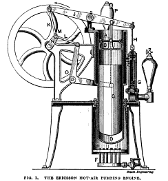
In the accompanying Fig I the Ericsson hot air pumping engine is shown in section The furnace which may be for wood coal oil or gas is at E The power piston is at B and is made a close working fit in the cylinder The piston C however fits loosely in the cylinder so that the heated air can pass upwards by its sides Its office is that of displacement only having a motion which brings the heated air charge to the top of the cylinder where it expands and drives the piston B upwards The piston B is connected to the crank N by the walking beam J and connecting rod K and the displacement piston is connected to the same crank by the forked bell crank O and connecting rod L The result of this mechanical arrangement is practically the same as if the two pistons were connected to separate cranks which were set 90 degrees apart The action in its simplest expression is that a charge of air is heated in the chamber D and expands driving the piston B upwards The water jacket then abstracts the heat and allows compression to take place with a less expenditure of power than is obtained by expansion
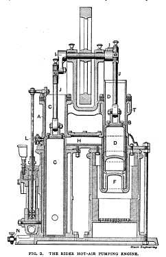
The difference between the power of the expansion stroke and that required for compression is the available power of the engine The displacement piston C transports the hot air from the region of the fire to a place where a closely fitted piston is practicable and where a water cooling effect is obtainable In the Stirling hot air engine a regenerator was used as was also the case in the Ericsson marine engine mentioned but no regenerator is used on the pumping engine The regenerator consisted of thin sheet plates of copper or brass located so that the air in going to and from the working piston passed over them The result is that the plates abstract some heat from the charge while traveling to the working cylinder and then gives it up on its return This arrangement favors the rapid reheating of the air and allows of greater speed of the engine The re heater is a feature of the Rider hot air engine shown in Fig 2 The reheater is at H the power cylinder is at A with the piston at C and the displacement cylinder is at B with its piston at D The power cylinder is water jacketed as shown and the displacement cylinder is water jacketed at the top to preserve the packing which otherwise would be destroyed by the heat The two pistons are connected to the same shaft by cranks set at 90 degrees so that the relative movements of the pistons are the same as in the Ericsson type but the displacement piston has a different action as it not only displaces the air charge but also increases and decreases the capacity of the chamber an action which does not take place in the Ericsson form
A feature of the hot air engine which does not allow of the greatest economy is that the water jacket is as efficient in cooling the hot air charge when it is entering the working cylinder as when leaving it and to favor cooling action it is necessary to present the cooling surface in a way that is detrimental in its initial action This can be clearly seen in the sectional view of the Rider engine which shows that the incoming hot air passes in a thin stream down between the water jacket and the piston There does not appear to be any simple method for overcoming this defect and this is therefore one disadvantage that operates to make the hot air engine an impracticable motor for large powers
The water pump is shown in section at the side in each cut and as stated previously the pumping of water is the sole use for which these interesting motors are intended
The connecting rod of the Rider engine is shown in Fig 3 in section so that the scheme for simultaneous adjustment of the crank and wrist pin boxes may be understood The ends of the rod are connected by the tube F through which extends the rod E The adjustment is effected by forcing the wedge D to the right or left as desired A movement to the right forces the brass C at the upper end against its pin and at the same time the rod E has the same action on the lower brass C Since the working stroke is always in the direction to compress the connecting rod brasses are only provided to take the compressive action
Altogether the hot air engine is an interesting machine and one that will well repay considerable study Although as pointed out they will probably never be practicable machines for power their usefulness in minor applications will undoubtedly cause a more extended use in the future


