User:Ckurtz/Mechanical Oscillator / Reciprocating Engine
The Mechanical Oscillator / Reciprocating Engine
Overview
The Mechanical Oscillator is a constant period resonance device designed to operate at high oscillation frequencies, with the low mass and extremely short stroke associated with such devices.
Components
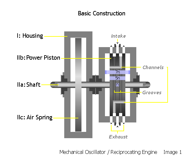
Basic components consist of (I) a Housing containing (II) a single moving unit composed of three parts: A: a Shaft extending completely through the housing, upon which is fixed: B: a power Piston, and C: an Air Spring.
The power Piston itself can be viewed as being composed of five equal longitudinal sections (5n), with two circumferential grooves separating the end sections from the central section.
Matching this construction, the Cylinder bore has precisely centered longitudinally around it a circumferential band composed of five sections each also 1n in width. The two end sections, each containing a Cylinder Exhaust Port, and the center section, containing the Cylinder Inlet Port, are separated from one another by two solid bands. Each Port opening is precisely centered on its section, but is cut slightly narrower (e.g. if n = 10 mm then each port could be 8 mm in width).
Operation
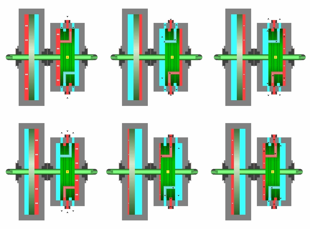
The Air Spring uses compression of atmospheric air to provide the resonance cushion of compressed gas, which in conjunction with the alternating impulses of the motive fluid against the power Piston controls its oscillations by slowing, stopping, and reversing its motion.
The power Piston also functions as a virtual spool valve controlling the in-flow and out-flow of the motive medium: steam (not known if wet steam is appropriate) or gas under pressure. In this valving capacity when at Null Center the power Piston's two End sections block the two Cylinder Exhaust Ports, while the Piston's Center section blocks the Cylinder Inlet Port. Movement in either direction unblocks the ports and directs the in-flow of the motive fluid alternatively from one cylinder face to the other.
The power Piston's valving functions necessitates a Piston throw of 1n in either direction requiring a minimum Cylinder internal length of at least 7n. (The accompanying images show an additional .5n on each end for cushioning because I am unsure if it is require – it probably isn't.)
During operation, the two power Piston Grooves act as plenums enhancing communication with the Cylinder Ports and the power Piston's internal fluid Channel rim ports, which are located in the Grooves. The Grooves alternate between the Cylinder's inlet port and the exhaust port opposite the piston face their Channel communicates with. Together the grooves and fluid channels serve as both inlet and exhaust ducts. The accompanying images show the top Piston Channel communicating with the left end of the Cylinder exhausting through the right Cylinder Exhaust Port, while the lower Piston Channel communicates with the right side of the Cylinder and exhausts through the left Cylinder Exhaust Port. A single pair of channels is shown for simplicity's sake; however, two pair would provide superior ventilation and load distribution.
The exact dimensions of the Air Spring would be a matter of empirical testing and adjustment to the selected motive fluid pressure and load range. This should be made easier by the fact that the Air Spring was deliberately designed as a 'leaky' pneumatic device allowing for wide latitude in adjustments.
Summary
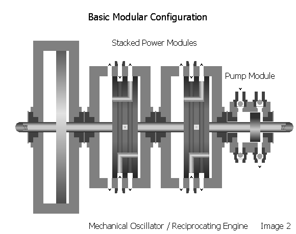
From all indications the Mechanical Oscillator is a very durable, low maintenance, high efficiency, easy to manufacture, low cost design which eliminates a multitude of parts, e.g. valves, cranks, fly wheels, load bearings, etc., and the accompanying parasitic losses normally associated with piston steam engines. Its elegant minimalist design was also envisioned as an adaptable platform to allow for stacking additional power modules and the use of various application modules; e.g. electrical generator, compressor, hydraulic pump, etc. It can operate in either the horizontal or vertical positions.
Patents
The patents covering the Mechanical Oscillator / Reciprocating Engine are in the public domain:
1894-01-02, US Patent 511,916 Electrical Generator
1894-02-06, US Patent 514,169 Reciprocating Engine
1894-04-10, US Patent 517,900 Steam Engine
1920-02-03, US Patent 1,329,559 Valvular Conduit


