The Liberator Full Release - Mechanical Fabrication: Difference between revisions
(→Frame) |
|||
| Line 14: | Line 14: | ||
==Structure== | ==Structure== | ||
The frame is design-for-disassembly. 1/2" bolts, grade 8, are used to hold the frame together. The main cylinder attaches to the bottom of the frame, and the opposing members are at the top of the frame. These sets of frame members withstand the entire pressure of the cylinder, 20 tons, with the use of 8 bolts. Thus, each bolt needs to withstand about 5,000 lb of shear force. The area of a 1/2" bolt (.2 sq in) at over 100ksi strength, indicates 20,000 lb shear force per bolt, or a safety factor of 4. The middle set of structural u-channel members do not undergo shear force, but only expansion force of the soil as it is pressed in the compression chamber. | |||
The structural members of the frame are 8 in number. The verticals (2), bottom cylinder support (2), opposing support (2), and compression chamber (2). There are 2 non-structural u-channels (8" wide), which close the bottom part of the compression chamber, with little force acting against them. These are 1/4" thick, while all the other structural members are 7/16" thick. | |||
==Cylinder Attachment== | ==Cylinder Attachment== | ||
==Sensor Assembly== | ==Sensor Assembly== | ||
Revision as of 21:25, 31 May 2010
Frame
The frame consists of 7/16" thick, 6" wide u-channel. The frame is the same as that found in Prototype 1. You can use that as a fabrication guide. See the pictures 1-3 of CEB_Prototype_1_Fab.
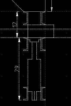
The Liberator Beta v2.0 is fabricated as follows. First, see the technical drawing for the overview:

The u-channels are shown around the cylinder and below the hopper.
Here are some fabrication pictures:
Structure
The frame is design-for-disassembly. 1/2" bolts, grade 8, are used to hold the frame together. The main cylinder attaches to the bottom of the frame, and the opposing members are at the top of the frame. These sets of frame members withstand the entire pressure of the cylinder, 20 tons, with the use of 8 bolts. Thus, each bolt needs to withstand about 5,000 lb of shear force. The area of a 1/2" bolt (.2 sq in) at over 100ksi strength, indicates 20,000 lb shear force per bolt, or a safety factor of 4. The middle set of structural u-channel members do not undergo shear force, but only expansion force of the soil as it is pressed in the compression chamber.
The structural members of the frame are 8 in number. The verticals (2), bottom cylinder support (2), opposing support (2), and compression chamber (2). There are 2 non-structural u-channels (8" wide), which close the bottom part of the compression chamber, with little force acting against them. These are 1/4" thick, while all the other structural members are 7/16" thick.