The Liberator Full Release - Mechanical Fabrication
Introduction
(last updated 6.2.10)
This text, in conjunction with pictures and videos, constitutes complete fabrication documentation. The product is The Liberator Beta v2.0 automatic CEB press, capable of producing 13-16 bricks per minute. All the .dxf files are here. See The Liberator Packing List to identify the parts discussed below.
Frame
The frame consists of 7/16" thick, 6" wide u-channel. The frame is the same as that found in Prototype 1. You can use that as a fabrication guide. See the pictures 1-3 of CEB_Prototype_1_Fab.
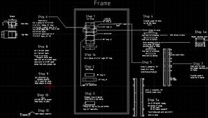
The Liberator Beta v2.0 is fabricated as follows. First, see the technical drawing for the overview:
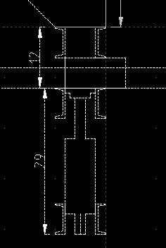
The u-channels are shown around the cylinder and below the hopper.
Frame
The frame is design-for-disassembly. 1/2" bolts, grade 8, are used to hold the frame together. The main cylinder attaches to the bottom of the frame, and the opposing members are at the top of the frame. These sets of frame members withstand the entire pressure of the cylinder, 20 tons, with the use of 8 bolts. Thus, each bolt needs to withstand about 5,000 lb of shear force. The area of a 1/2" bolt (.2 sq in) at over 100ksi strength, indicates 20,000 lb shear force per bolt, or a safety factor of 4. The middle set of structural u-channel members do not undergo shear force, but only expansion force of the soil as it is pressed in the compression chamber.
The structural members of the frame are 8 in number. The verticals (2), bottom cylinder support (2), opposing support (2), and compression chamber (2). There are 2 non-structural u-channels (8" wide), which close the bottom part of the compression chamber, with little force acting against them. These are 1/4" thick, while all the other structural members are 7/16" thick.
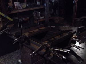
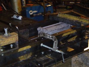
Fig 1 shows the frame members, being aligned for Transfer Punching holes for the 1/2" bolts. The dimensions of the u-channel members are shown in the technical drawing referred to above - see frame_overview.dxf (94.2 KB) from 01/20/2010 03:36 pm at Open+Pario.
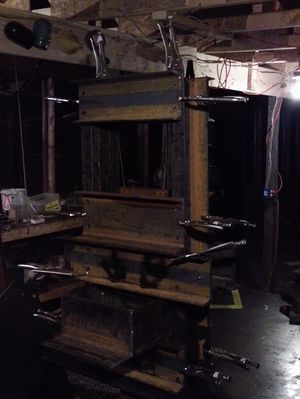
Clamp all the structural members together, while fitting the soil drawer (shown further down) to assure correct spacing. Transfer punch all the holes with machine positioned vertically so that all holes are accessible. See Fig. 2.
Holes in the eight, short, u-channel members have already been punched with a 120 Ton Hole Puncher or similar, with capacity to punch 9/16" holes. The holes are 9/16" - as 1/2" punched holes would be slightly undersized.
The two, vertical u-channels are then drilled at the location of the transfer punch marks.
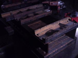
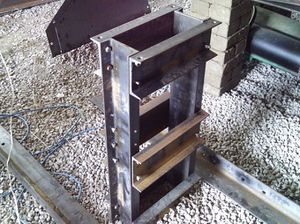
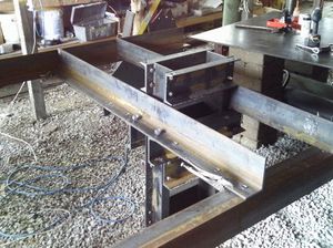
After drilling, the frame is bolted together, Fig. 3. After bolting the frame can stand vertically, ready for attachment of the arms, Fig. 4.
Cylinder
The main cylinder is a 5"x8"x2.5" (bore-stroke-rod) cylinder.The main cylinder has a press foot fabricated from 2 plates, each 1" thick, welded on top of the cylinder rod to make the press foot. The press foot consists of one 6"x12" plate, with the second plate being 4"x10". These 2 plates are welded together. Before these plates are welded together, the smaller plate is torched out to accommodate a 1.5", fine-threaded nut, and the nut is welded into this plate. The press foot is then screwed on to the rod, where the cylinder used has a rod with 1.5" fine threads and a shoulder. The shaft of the cylinder used is 2". In future versions, we need to source a cylinder with a 2.5" rod, as the 2" rod will bend in the present configuration in the condition of uneven soil loading into the compression chamber. For this reason, the press foot was modified in Maureen's machine - by welding 6" guides under the press foot to prevent the press foot from bending with uneven loads.
It appears that the best strategy for attaching the press foot would be to weld a 1/2" wall DOM shoulder around the cylinder rod, by welding on the inside of this shoulder at the top of the cylinder rod, and then welding this DOM to the press foot, and using gussets towards the long way of the press foot.
Cylinder Attachment
Once the main frame is bolted together, the cylinder is fitted, Fig. 5.
The cylinder is extended to its fully-extended position (by using air pressure or hydraulic flow), and the location of the bottom clevis mounting position is selected accordingly. The position of the clevis mount may be selected such that the press foot tops out at 1/16" or 1/8" above the table surface, to accommodate slight deformation of the frame over time. The table surface is defined as the bottom surface of the soil-loading drawer. The 1/16" or 1/8" is compensated by the location of the position sensors.
The bottom of the cylinder is attached to the bottom, horizontal u-channels via a 1" cylinder pin. 1/2" wall, drawn-over-mandrel (DOM) tubing is welded to the bottom u-channels, and it butts up right to the cylinder clevis. The pin is 8" long, and the DOM is 2.5" and 3" long, with the longer DOM drilled to accommodate a 1/8" pin for holding the cylinder pin in place. The 1" pin is drilled also to accommodate the small pin.
The hole for the cylinder pin DOM is torched with an acetylene torch, and the DOM is welded in place as needed.
In this video, we show how we started with 1 1/16" holes punched out with a hole puncher, as the bottom cylinder mount. It turns out that these are too large and sloppy. The pin ends up bending with these, so so we torched them off, and remounted the bottom of the cylinder with tightly-fitting DOM:
Sensor Assembly
Arms, Legs, and Feet
The arms are made from 4"x6"x3/8" angle. See the file shown in Fig. 6 for the cut list for the arms. Note the 3/4" hole locations - used to attach: the arms to the frame (4 holes); tables to the arms; secondary cylinder to the arms; second set of arms to the first set of arms; and hopper supports to arms. (Hopper supports hole must be modified as of 6.13.10)
The legs are 4 pieces of 2"x2" square tubing, with a hole for attaching the kill-switch wire.
The legs are attached to the arms by the 8 attachments, welded to the arms. The attachments are 8 pieces of 2.5"x2.5"x3/16" square tubing, with a hole torched in them, and with a 3/4" nut welded on to them.
The feet (see design file) are made of quarter inch plate, 10" square. The attachment is made with a welded nut, just like for the leg attachment.
Drawer
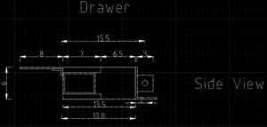
See Fig. 8.
Structure
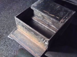
The drawer structural part consists of 2 pieces of steel, 1" thick, 7" wide - sandwiching a 4"x6"x1/4" square tube. This is the assembly against which pressing occurs, and it has to withstand a 20 ton force. There's an overhang to prevent soil from falling in front of the drawer, and a soil compartment benind it for loading soil. The cylinder attaches to a 4"x6" angle. The sides are 6"x1/4" steel, 13.5 inches long. The drawer, without rails, consists of a total of 10 steel sections. A picture is shown in Fig. 9.
For the rails, begin with the drawer_update.dxf at OpenPario. Note that the rails are a total of 30" long, and consist of a 1/2"x2" flat bar, with a 1/4"x2.5" bar welded on top as the rail, where the 1/2" hanging under the bar constitutes the rail. Note that this rail should stick out 1" in front of the 8" hood shown in the thumbnail, and the top of the rail should be even with the top surface of the drawer.
Sensor
The megnet holder part of the sensor assembly attaches via a 3/4" welded nut to the rail of the drawer.
